Note
Access to this page requires authorization. You can try signing in or changing directories.
Access to this page requires authorization. You can try changing directories.
In this part of the tutorial, you define entity types in digital twin builder (preview) and map data to entity instances. The entity types include:
- Distiller
- Condenser
- Reboiler
- Process
- Technician
- MaintenanceRequest
For each entity type, you configure how property and/or time series data is mapped from the sample tables to the entity instances' properties in digital twin builder.
Important
This feature is in preview.
Add the Distiller entity type
In this section, you define the first entity type in the sample ontology, Distiller.
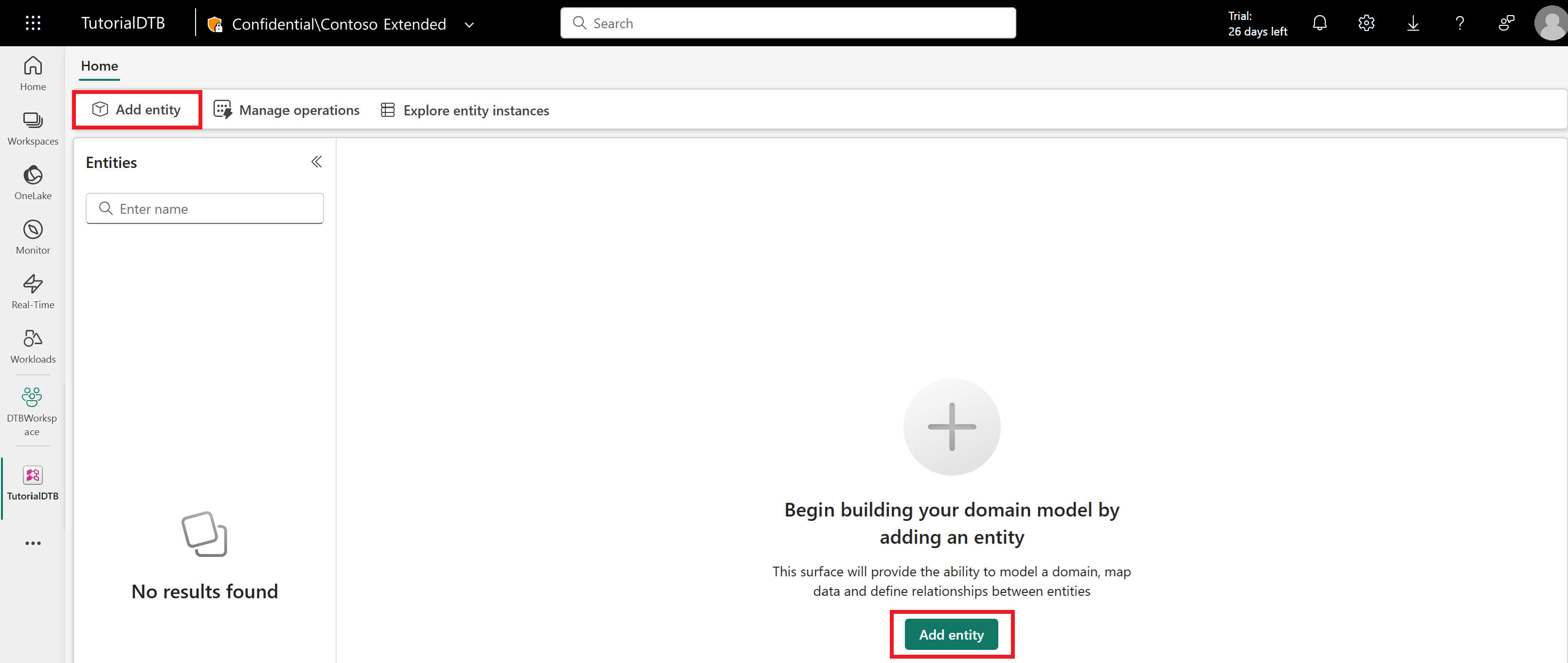
In the semantic canvas of digital twin builder (preview), select Add entity.
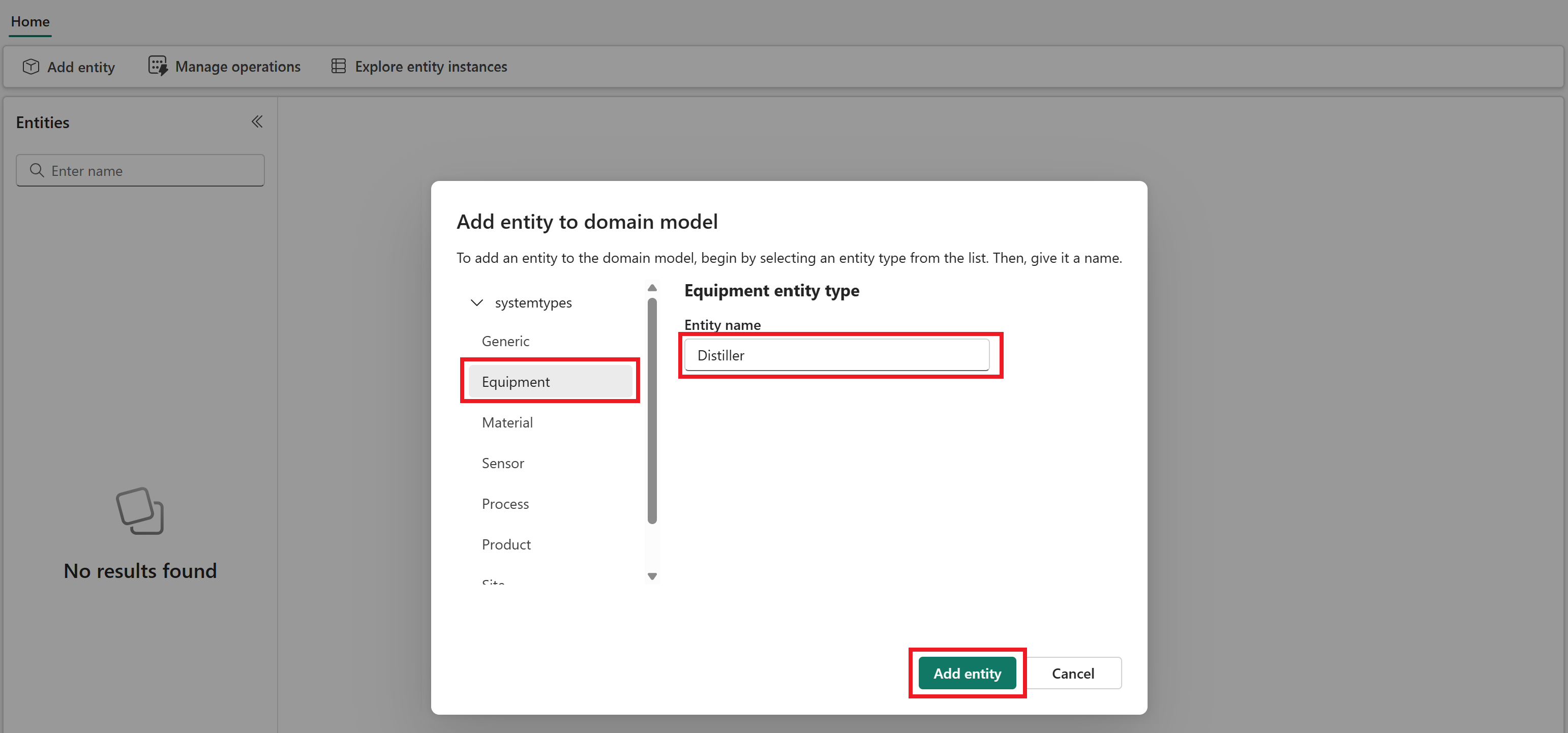
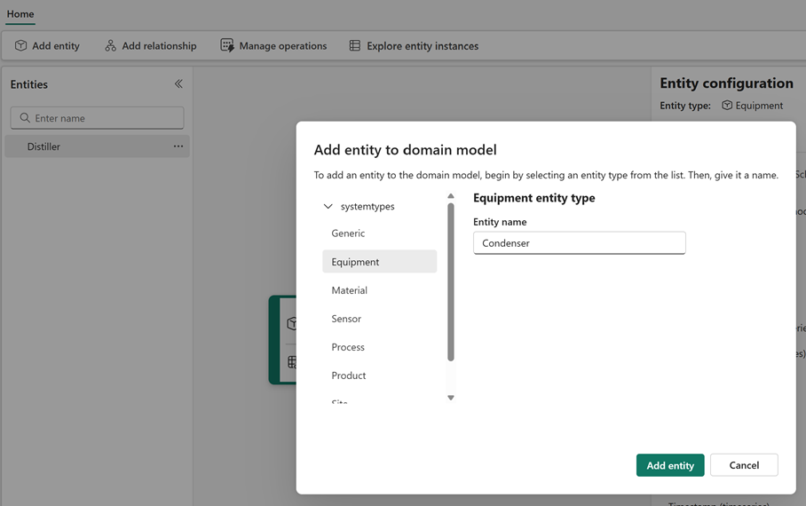
Select the Equipment system type. System types are built-in entity types that you can select when defining an entity type, to automatically associate it with a set of relevant properties that are common to objects of this type.
Enter Distiller for the entity type name and select Add entity.
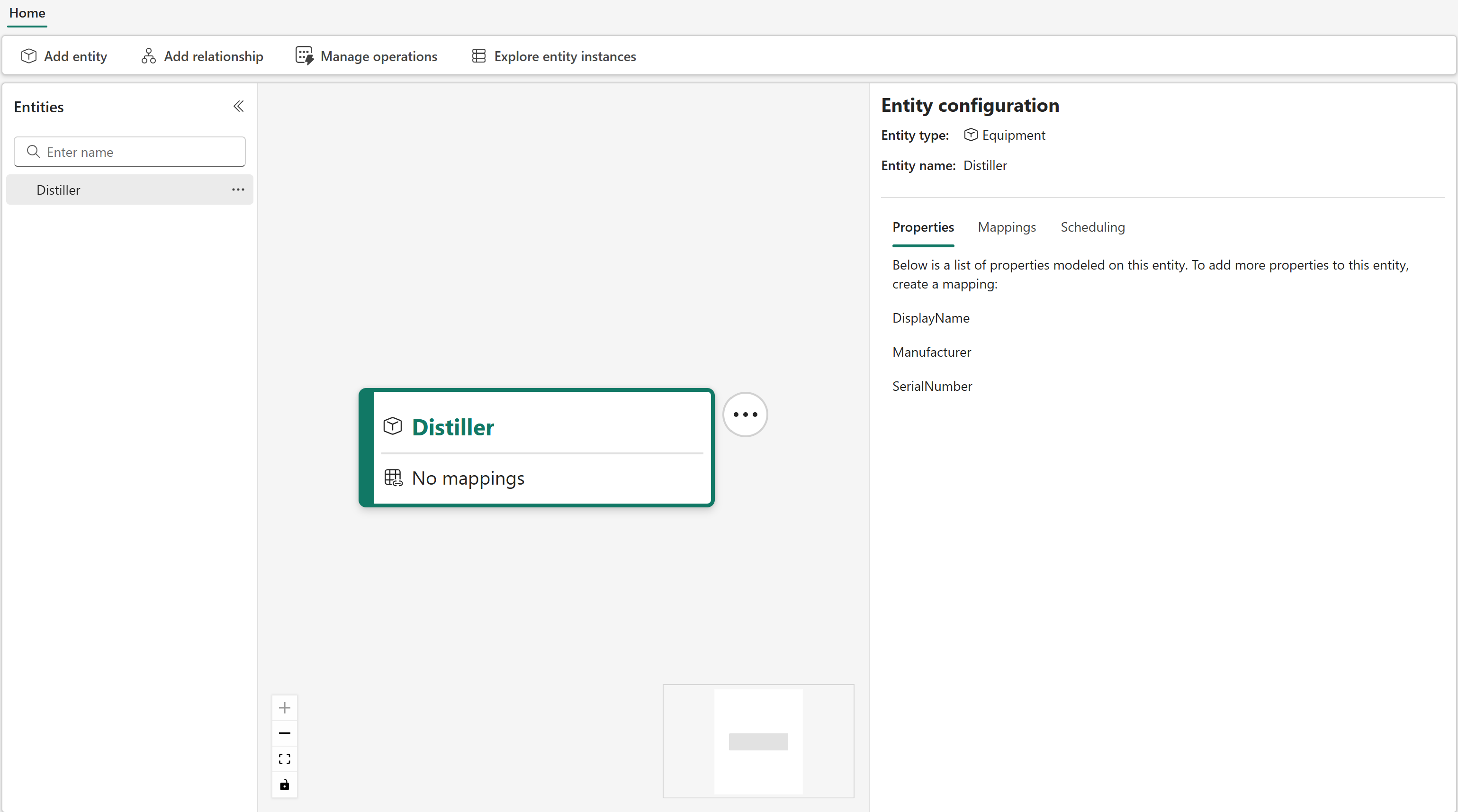
After a few minutes, the Distiller entity type is now visible on the canvas.
Map data to the Distiller
Next, map some data to your Distiller entity type.
The mapping feature in digital twin builder (preview) is the first step to creating an ontology with semantically rich entity types. During mapping, you hydrate your entity instances with data from various source systems.
You can add both time series and non-time series properties to an entity type. When mapping both types of property to an entity type, you must map at least one non-time series property before you can map time series properties. Then, link the non-time series and time series data together by matching a non-time series property from the entity type with a column from the time series data. The values in the time series column must exactly match data that's mapped to the entity type property.
Map non-timeseries properties
Start by mapping the asset metadata.
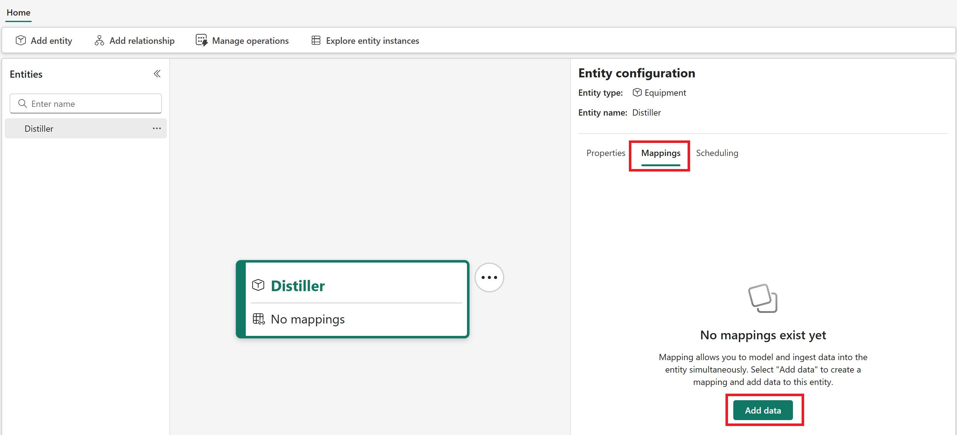
Select your entity type on the canvas or in the entity type list pane to open the Entity configuration pane.
In the pane, go to the Mappings tab. Select Add data to create a new mapping.
Open Select lakehouse table to select a data source for your mapping. From your tutorial workspace, select the GettingStartedRawData lakehouse and the assetdata table.
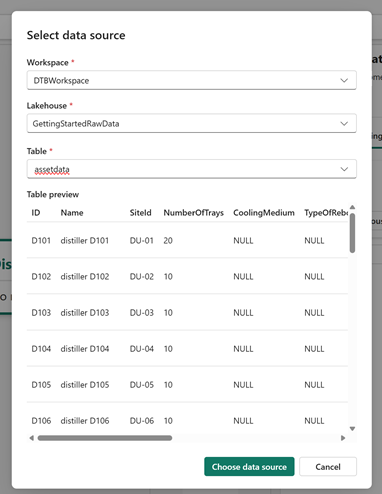
Optionally, wait for the data preview to load. Select Choose data source to confirm.
Next to your Source table choice, select No filter applied to add a filter to your source table mapping. Select the column Name, the operation Contains, and the value distiller (case-sensitive). Then select Apply.
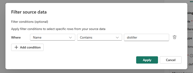
The button text now shows Filter applied.
Next, select the Property type of the data you're mapping. This first mapping deals with asset metadata for the Distiller entity type, so choose Non-timeseries properties.

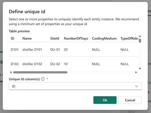
Under Unique Id, select the edit icon (shaped like a pencil) to choose a unique ID for your data. The unique ID is created out of one or more columns from your source data, and is used by digital twin builder to uniquely identify each row of ingested data. Choose ID as the unique ID for this data, and select Ok to save and close the modal.
Under Mapped properties, select the edit icon to map properties from your source table.
The Map properties pane lets you select a column from your source data on the left side, and map it to a new property on your entity type on the right side. By default, selecting a column name from the source data on the left side fills in the right side automatically with a matching name for the entity type property, but you can enter a new name for the property on the right side if you want the entity type property to be named something different than its name in the source data.
Define the following property mappings:
Where DisplayName is automatically provided on the right side as a property to map, select Name as the source column on the left side.
Leave Manufacturer and SerialNumber unmapped.
Select + Add entity property to add a new property. Select ID as the source column on the left side, and edit the property on the right side to be DistillerId.
Add a new entity type property. Select SiteId as the source column on the left side, and leave the SiteId that fills automatically as the property to map on the right side.
Add a new entity type property. Select NumberOfTrays as the source column on the left side, and leave the NumberOfTrays that fills automatically as the property to map on the right side.
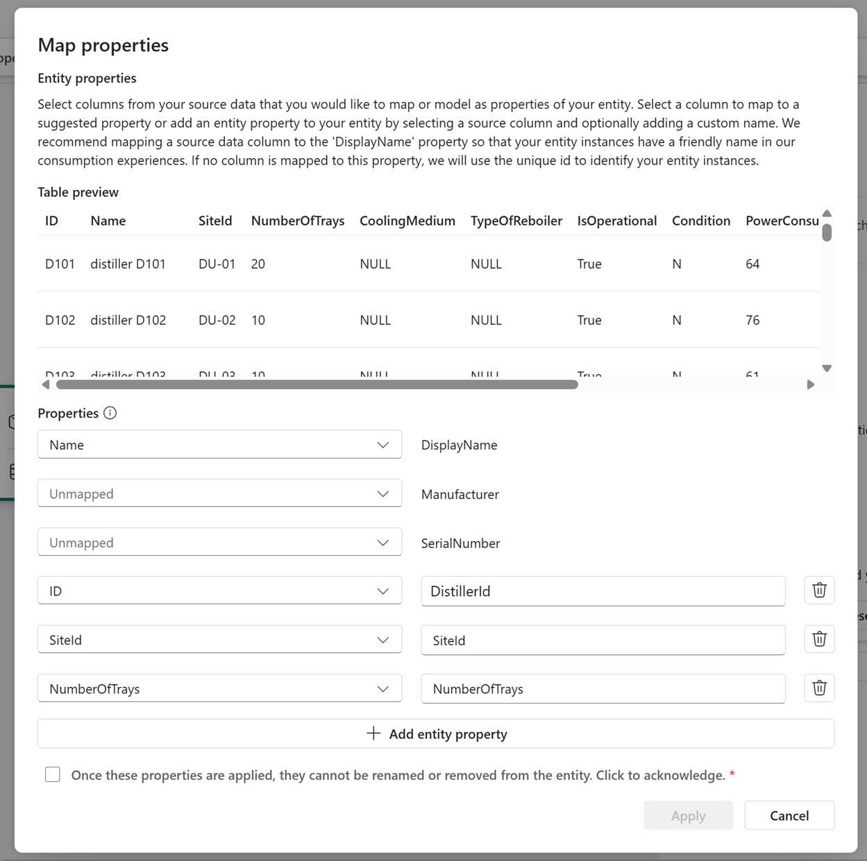
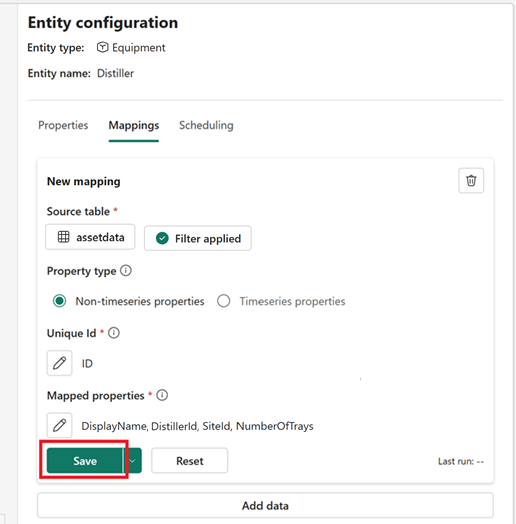
Check the box to acknowledge that once these properties are applied, they can't be renamed or removed from the entity type.
Select Apply to save your properties. Then select Save to save your mapping.
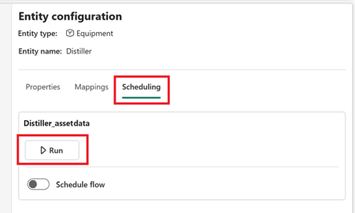
Go to the Scheduling tab to run your mapping job. Under the name of your mapping job, select Run.
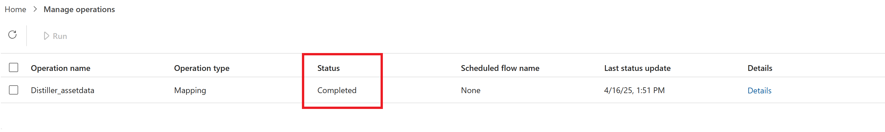
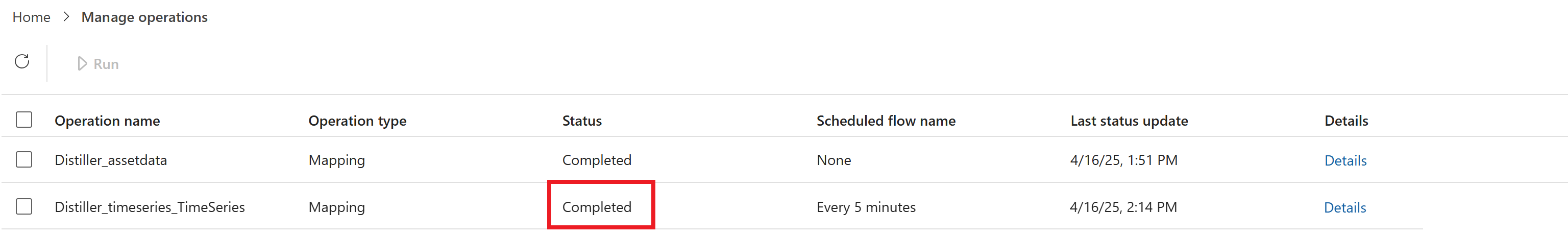
Check the status of your mapping job in the Manage operations tab. Wait for the status to say Completed before proceeding to the next section (you might need to refresh the content a few times).
When the mapping is done running, entity instances are created and hydrated with the non-time series data.
Map time series properties
Next, map some time series data. For the Distiller entity type, there are four time series properties coming from the time series data table that need to be added. After they are added, you link the time series data to the entity instances that you mapped in the previous step, by specifying a link property that exactly matches values across the time series and non-time series data.
Select Home to return to the semantic canvas, and reselect the Distiller entity type. In the Entity configuration pane, reopen the Mappings tab.
Select Add data to create a new mapping for the time series data.
Open Select lakehouse table to select a data source for your mapping. From your tutorial workspace, select the GettingStartedRawData lakehouse and the timeseries table.
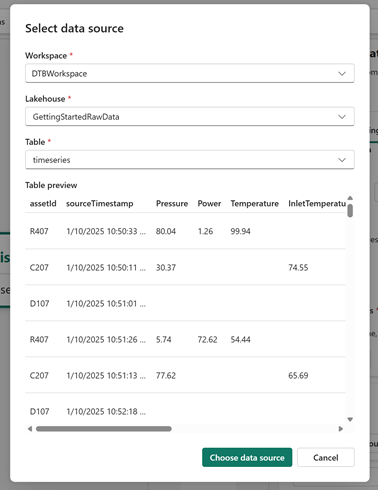
Optionally, wait for the data preview to load. Select Choose data source to confirm.
Next, select No filter applied to add a filter to your source table mapping (make sure you're still editing the new mapping, not the first mapping). Select the column assetId, the operation Contains, and the value D (case-sensitive). Then select Apply.
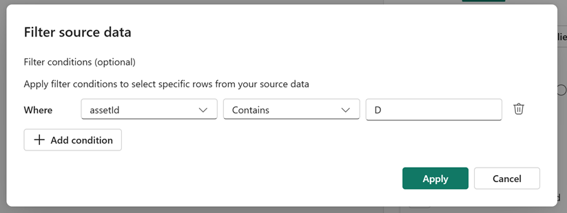
The button text now shows Filter applied.
For the Property type, choose Timeseries properties.
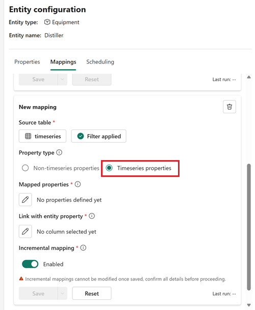
Under Mapped properties, select the edit icon.
Where Timestamp is automatically provided on the right side as a property to map, select sourceTimestamp as the source column on the left side.
Use + Add entity property to add four time series properties from these source columns: RefluxRatio, MainTowerPressure, FeedFlowRate, and FeedTrayTemperature. Leave the default matching names that populate on the right side.
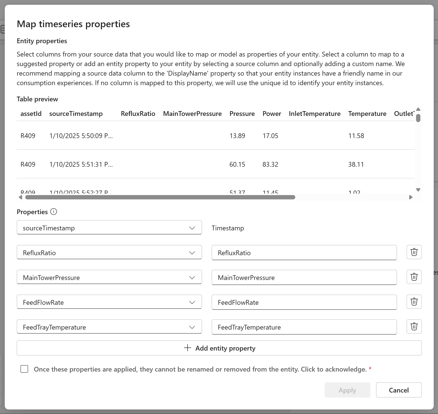
Check the box to acknowledge that once these properties are applied, they can't be renamed or removed from the entity type.
Select Apply.
Next, link the time series data to the entity instance data. Under Link with entity property, select the edit icon. This process requires you to select an entity type property and a matching column from your time series data table. The source column selected from the time series data must exactly match data that is mapped to the selected property on the entity type. This process ensures correct contextualization of your entity instance data and time series data.
For Choose entity property, select DistillerId. Under Select column from timeseries data..., select the assetId column from your time series data.
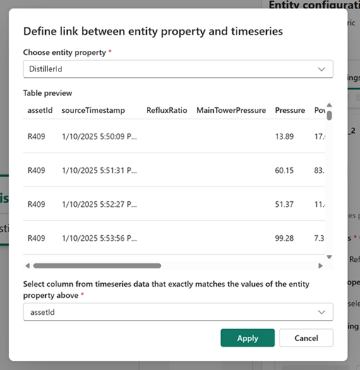
Select Apply to save and close the modal.
Make sure Incremental mapping is enabled, then select Save to save your mapping job. Confirm when prompted that you want to save the incremental mapping.
Go to the Scheduling tab to run your mapping job. Locate the new mapping job (it ends in TimeSeries) and select Run.
Next, add a schedule for the timeseries mapping so that it refreshes the data automatically. Here you create a schedule that runs every five minutes.
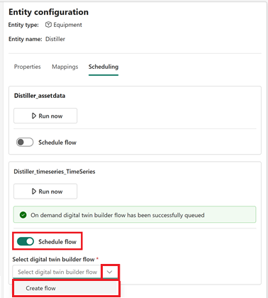
Go to the Scheduling tab. Under the name of your time series run, toggle on the switch for Schedule flow. This displays a schedule selector. Expand the dropdown menu and select Create flow.
For the Flow name, enter Every 5 minutes. Select Create.
Select the new Update flow schedule button to configure scheduled run details.
In the Every 5 minutes settings, configure these options:
- Scheduled run: On
- Repeat: By the minute
- Every: 5 minute(s)
- Start date and time: Pick today's date and time.
- End date and time: Pick the time 10 minutes from now.
- Time zone: Pick your time zone.
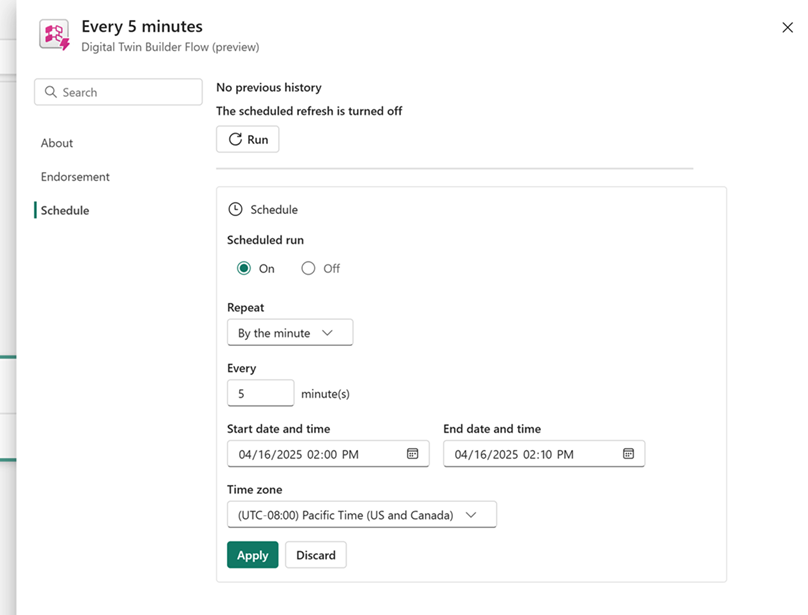
Select Apply and close the schedule configuration.
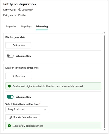
You see the schedule reflected in the Entity configuration pane.
Now all properties of the Distiller are mapped. To verify, select the Properties tab and confirm that your entity type looks like this in the semantic canvas:
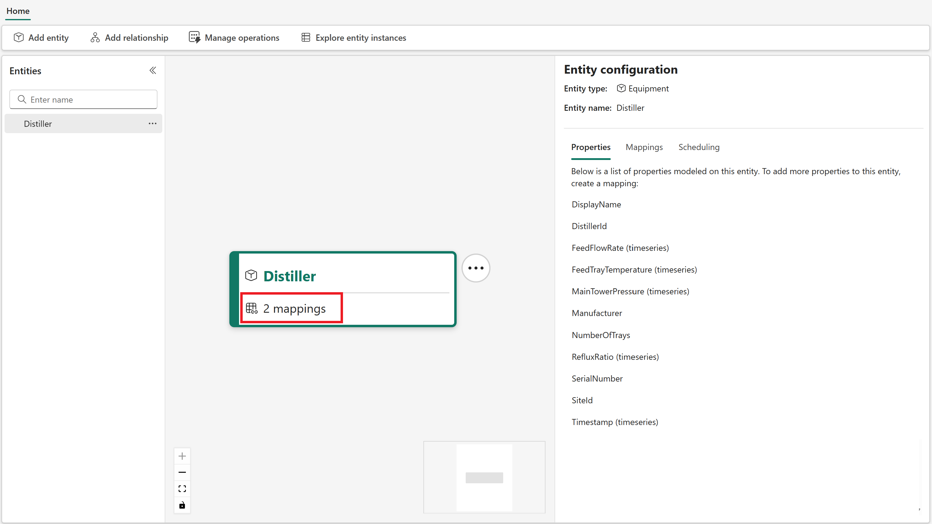
Check the status of your time series mapping in the Manage operations tab. Wait for the status to say Completed before proceeding to the next section (you might need to refresh the content a few times).
Tip
If you see a status of Failed for your mapping job, try rerunning it. If you continue to experience issues, see Troubleshooting digital twin builder (preview) for help.
Now the Distiller entity type and its mappings are complete.
Add other entity types
Now that the Distiller entity type is created, it's time to populate the ontology with the remaining entity types from the source data: Condenser, Reboiler, Process, Technician, and MaintenanceRequest. The entity type creation steps are similar to the steps for the Distiller entity type, but the property specifics differ for each entity type.
Condenser
To create the Condenser entity type:
In the semantic canvas, select Add entity from the ribbon. Using the Equipment system type, create an entity type named Condenser.
In the Mappings tab of the new entity type, select Add data. There are two mappings for this entity type: one non-timeseries mapping and one timeseries mapping.
Create the following mappings. Remember that all source tables are in your tutorial workspace and the GettingStartedRawData lakehouse.
Source table Filter (case-sensitive) Property type Link/Unique ID Mapped properties Save and run notes assetdata Where Name Contains condenser Non-timeseries properties Unique Id: ID - Map Name as DisplayName
- Leave Manufacturer and SerialNumber unmapped
- Map ID as CondenserId
- Map SiteId as SiteId
- Map CoolingMedium as CoolingMedium
- Map InstallationDate as InstallationDateAfter the mapping is created and saved, go to the Scheduling tab and run it, then verify its completion in the Manage operations tab.
You must run this non-timeseries mapping before creating the following timeseries mapping.timeseries Where assetId Contains C Timeseries properties Link entity property: CondenserId
Link timeseries column: assetId- Map sourceTimestamp as Timestamp (Required, case-sensitive)
- Map Pressure as Pressure
- Map Power as Power
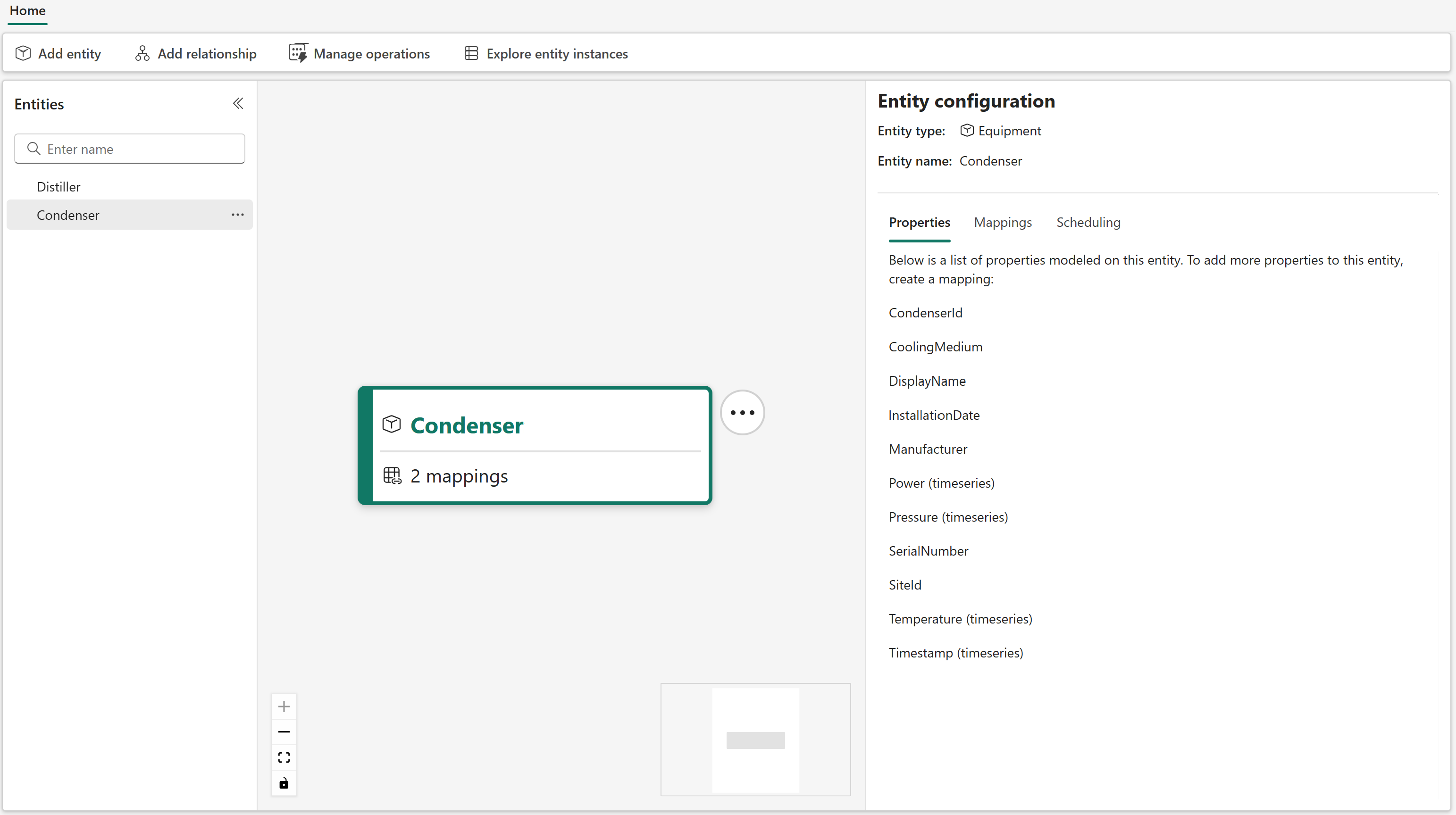
- Map InletTemperature as TemperatureMake sure incremental mapping is enabled, then save your mapping. Go to the Scheduling tab and run it. When you're finished mapping the Condenser, it should look like this:
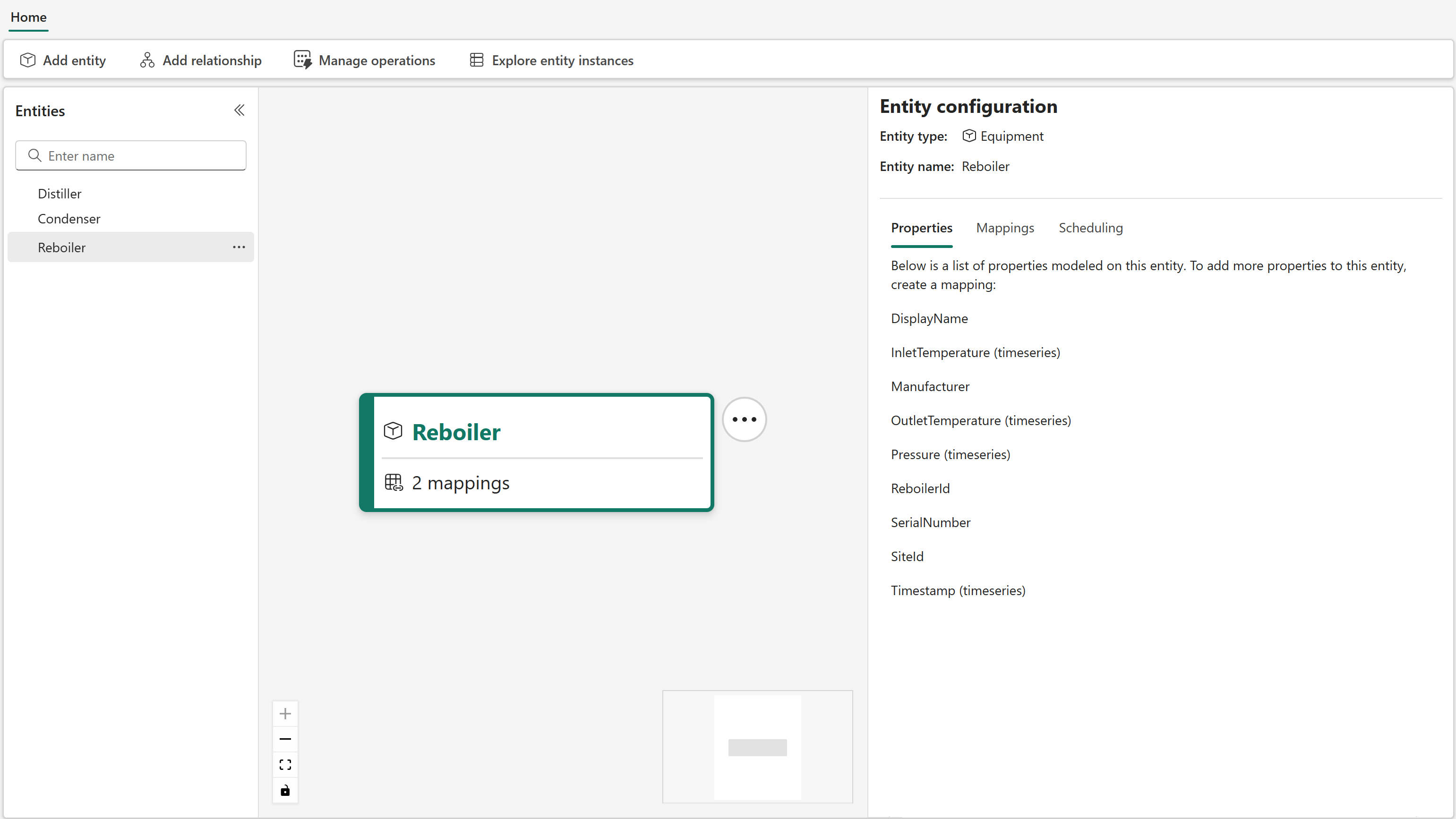
Reboiler
To create the Reboiler entity type:
In the semantic canvas, select Add entity from the ribbon. Using the Equipment system type, create an entity type named Reboiler.
In the Mappings tab of the new entity type, select Add data. There are two mappings for this entity type: one non-timeseries mapping and one timeseries mapping.
Create the following mappings:
Source table Filter (case-sensitive) Property type Link/Unique ID Mapped properties Save and run notes assetdata Where Name Contains reboiler Non-timeseries properties Unique Id: ID - Map Name as DisplayName
- Leave Manufacturer and SerialNumber unmapped
- Map ID as ReboilerId
- Map SiteId as SiteIdAfter the mapping is created and saved, go to the Scheduling tab and run it, then verify its completion in the Manage operations tab.
You must run this non-timeseries mapping before creating the following timeseries mapping.timeseries Where assetId Contains R Timeseries properties Link entity property: ReboilerId
Link timeseries column: assetId- Map sourceTimestamp as Timestamp (Required, case-sensitive)
- Map Pressure as Pressure
- Map InletTemperature as InletTemperature
- Map OutletTemperature as OutletTemperatureMake sure incremental mapping is enabled, then save your mapping. Go to the Scheduling tab and run it. When you're finished mapping the Reboiler, it should look like this:
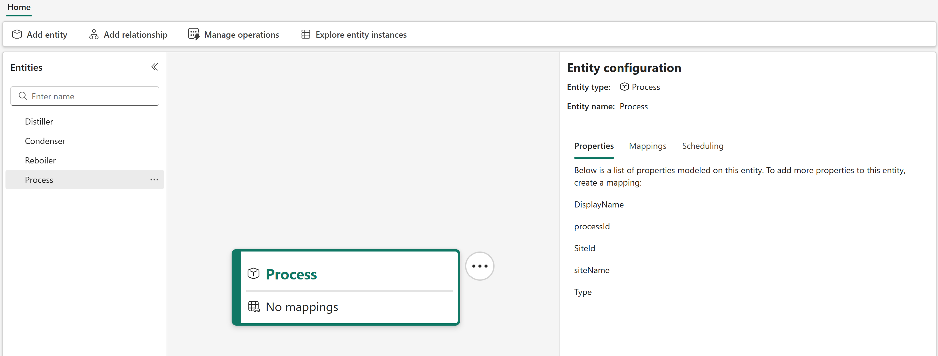
Process
To create the Process entity type:
In the semantic canvas, select Add entity from the ribbon. Using the Process system type, create an entity type named Process.
In the Mappings tab of the new entity, select Add data. There's one non-timeseries mapping for this entity type.
Create the following mapping:
Source table Filter (case-sensitive) Property type Link/Unique ID Mapped properties Save and run notes processdata None Non-timeseries properties Unique Id: processId - Leave DisplayName and Type unmapped
- Map siteName as siteName
- Map processId as processId
- Map siteId as SiteIdAfter the mapping is created and saved, go to the Scheduling tab and run it. When you're finished mapping the Process, it should look like this:
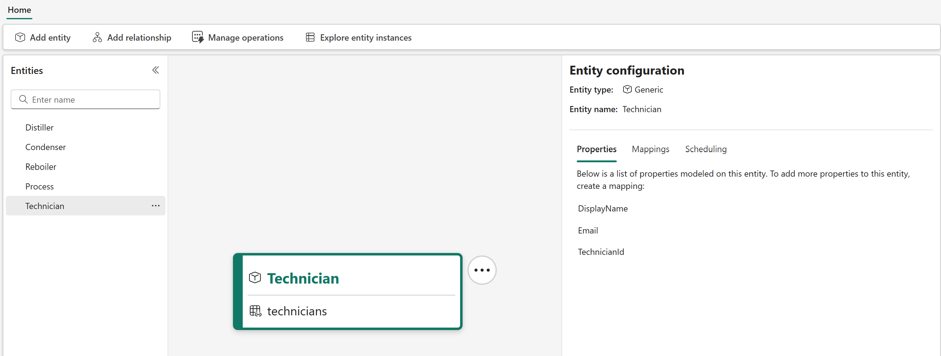
Technician
To create the Technician entity type:
In the semantic canvas, select Add entity from the ribbon. Using the Generic system type, create an entity type named Technician.
In the Mappings tab of the new entity, select Add data. There's one non-timeseries mapping for this entity type.
Create the following mappings:
Source table Filter (case-sensitive) Property type Link/Unique ID Mapped properties Save and run notes technicians None Non-timeseries properties Unique Id: Id - Map name as DisplayName
- Map email as Email
- Map Id as TechnicianIdAfter the mapping is created and saved, go to the Scheduling tab and run it. When you're finished mapping the Technician, it should look like this:
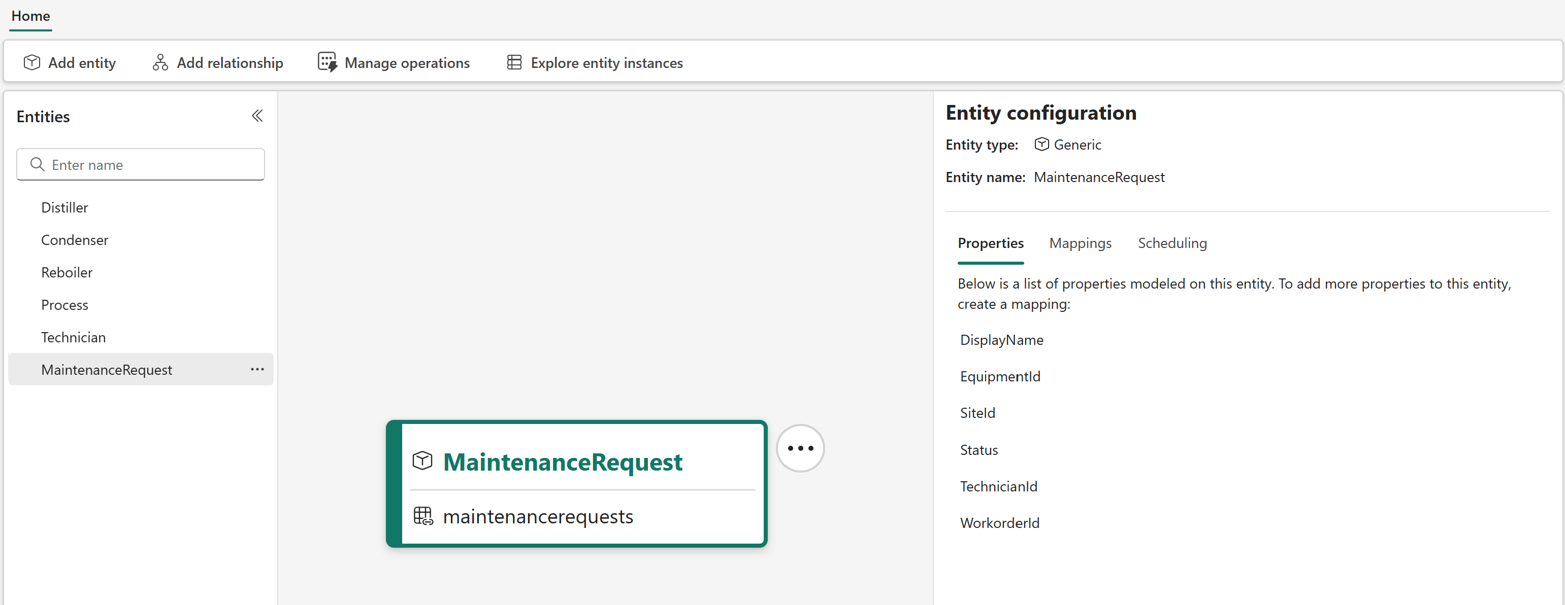
MaintenanceRequest
To create the MaintenanceRequest entity type:
In the semantic canvas, select Add entity from the ribbon. Using the Generic system type, create an entity type named MaintenanceRequest.
In the Mappings tab of the new entity, select Add data. There's one non-timeseries mapping for this entity type.
Create the following mappings:
Source table Filter (case-sensitive) Property type Link/Unique ID Mapped properties Save and run notes maintenancerequests None Non-timeseries properties Unique Id: WorkorderId - Leave the DisplayName property unmapped.
- Map EquipmentId as EquipmentId
- Map Site as SiteId
- Map Status as Status
- Map TechnicianId as TechnicianId
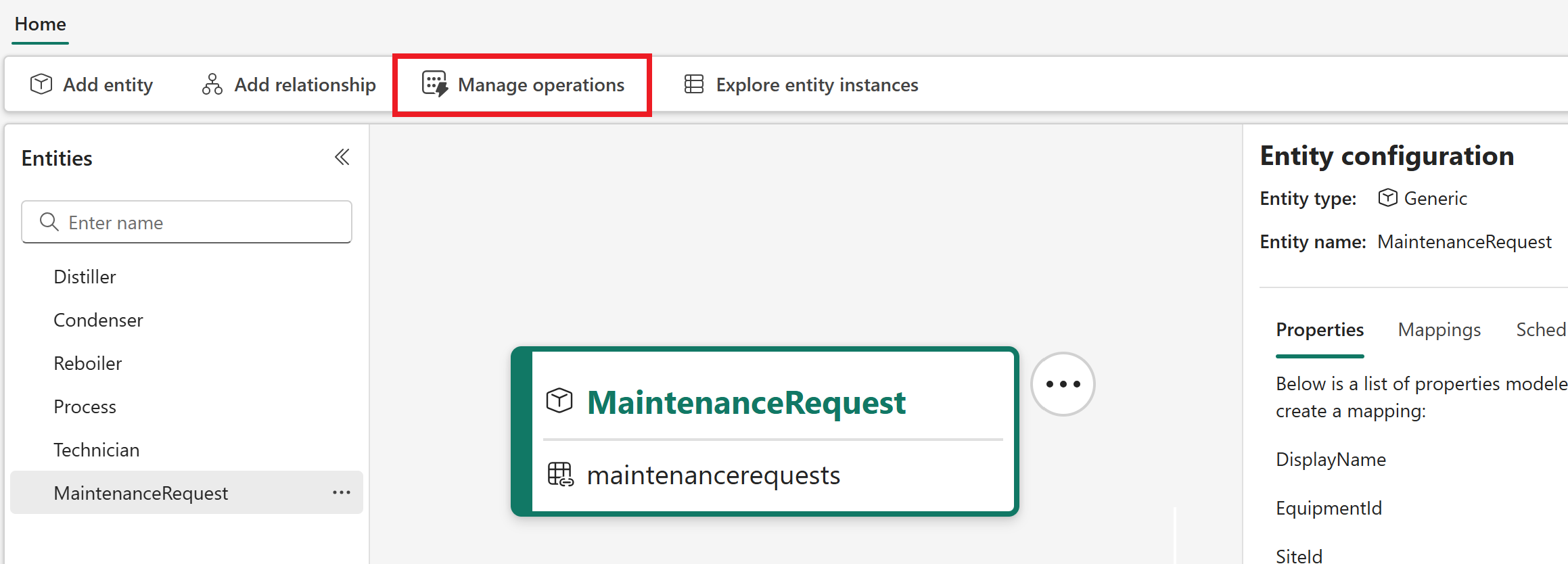
- Map WorkorderId as WorkOrderIdAfter the mapping is created and saved, go to the Scheduling tab and run it. When you're finished mapping the MaintenanceRequest, it should look like this:
Now all the entity types are created. Your semantic canvas should contain the following six entity types: Distiller, Condenser, Reboiler, Process, Technician, and MaintenanceRequest.
Check the status of your mappings
Now that all the entity type mappings are added, check the status of the mapping operations to verify that they completed successfully.
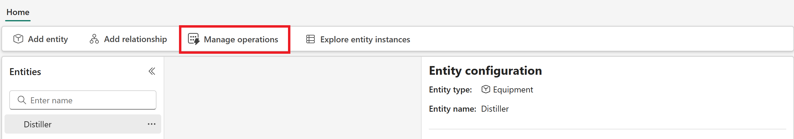
Select the Manage operations button.
The Manage operations tab shows a list of your operations alongside their status. You can use this page to know when all your mapping operations are successfully completed.
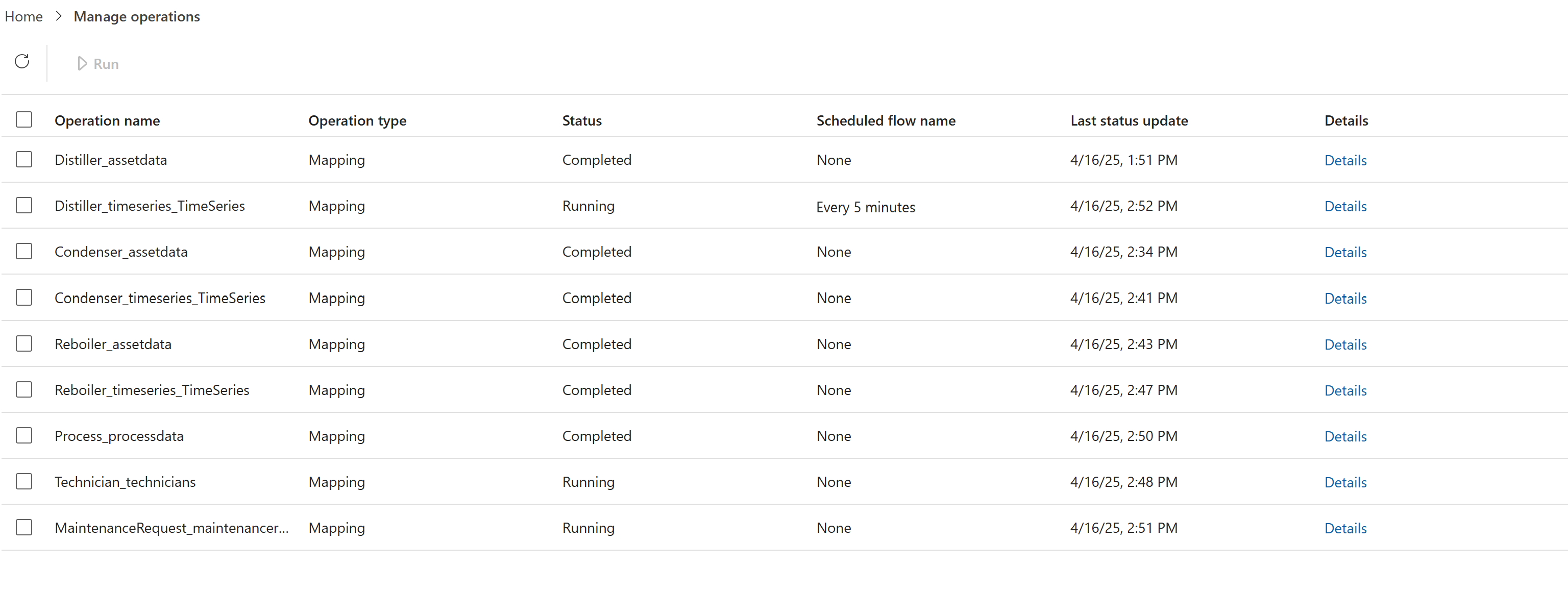
Wait for all mappings to complete before you move on to the next part of the tutorial.
Tip
If you see a status of Failed for a mapping job, try rerunning it. If you continue to experience issues, see Troubleshooting digital twin builder (preview) for help.