Note
Access to this page requires authorization. You can try signing in or changing directories.
Access to this page requires authorization. You can try changing directories.
In this part of the tutorial, you build a digital twin ontology that models the bus and bus stop data. You create a digital twin builder (preview) item, and define entity types for the buses and stops. Then, you map the data from the TutorialLH lakehouse to the entity instances, and define relationship types between the entity types to further contextualize the data.
Important
This feature is in preview.
Create new digital twin builder item in Fabric
Note
Recall from the tutorial prerequisites that digital twin builder (preview) must be enabled on your Fabric tenant.
Go to your Fabric workspace.
Select New item.
Search for the Digital Twin Builder (preview) item, and select it.
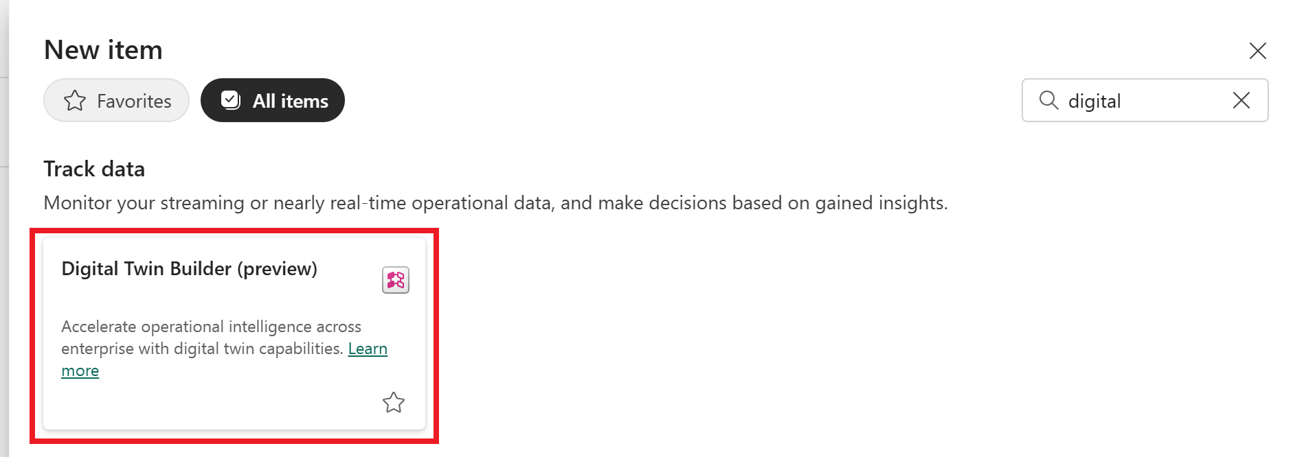
Name your item TutorialDTB and select Create.
Tip
Digital twin builder names can include numbers, letters, and underscores (no spaces or dashes).
Wait for your digital twin builder item to be created. Once your digital twin builder item is ready, it opens to the semantic canvas.
In the semantic canvas, you can add entity types and relationship types to define an ontology.
About entity types and relationship types
In digital twin builder (preview), an entity type is a category that defines a concept within a domain-specific ontology. The entity type definition serves as a blueprint for individual entity instances of that entity type, and specifies common characteristics shared across all instances within that category. Here you define two entity types for the sample scenario: Bus and Stop.
After you create an entity type, you can map data to it to hydrate the entity instances with data from various source systems. You can add both time series and non-time series properties to an entity type. When mapping both types of property to an entity type, you must map at least one non-time series property before you can map time series properties. Then, link the non-time series and time series data together by matching a non-time series property from the entity type with a column from the time series data. The values in the time series column must exactly match data that's mapped to the property on the entity type.
After your entity types are defined and mapped, you can create relationship types between them to define how they're related to each other. In this tutorial, a Bus goesTo a Stop.
Add Bus entity type
First, create a new entity type for the bus.
In the semantic canvas of digital twin builder (preview), select Add entity.
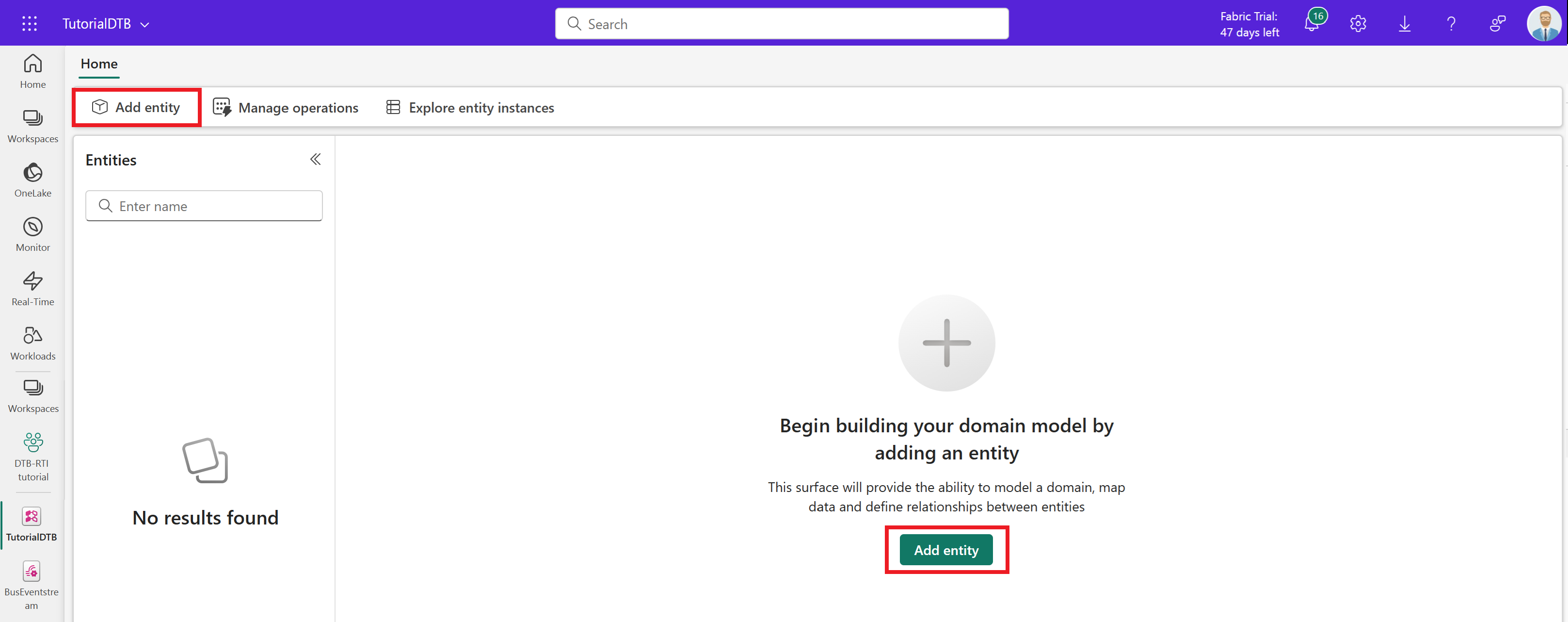
Leave the Generic system type selected, and enter Bus for the entity type name. Select Add entity.
The Bus entity type is created and becomes visible on the canvas.
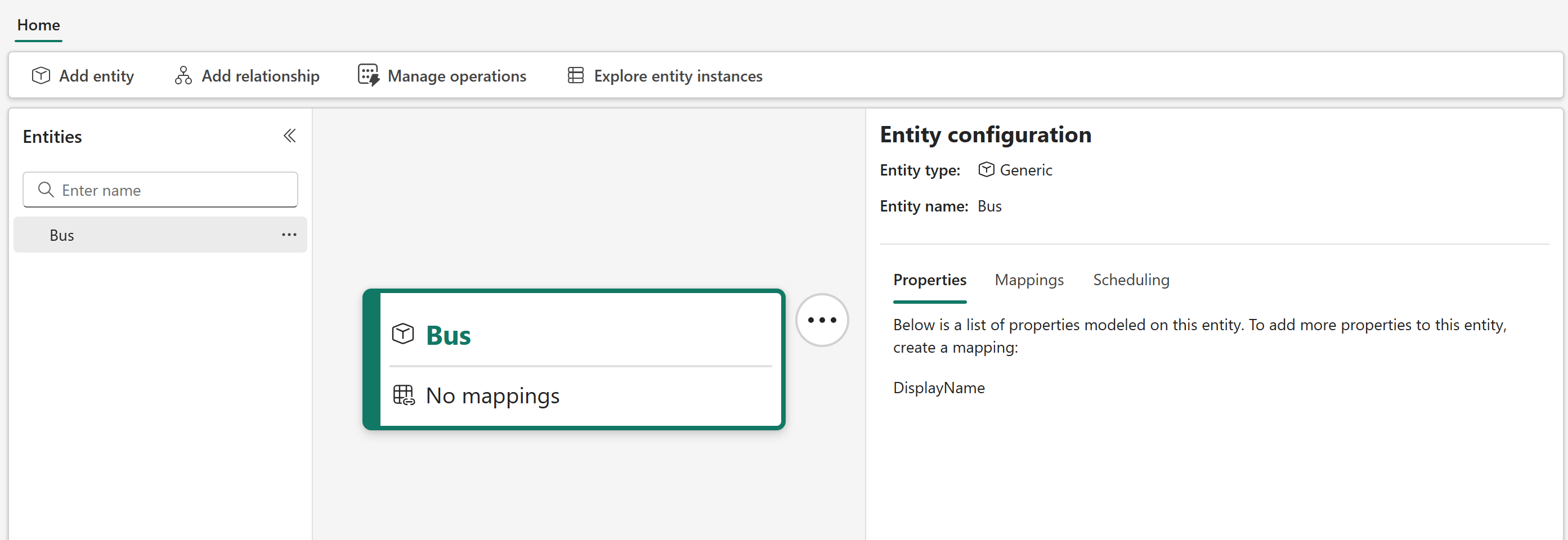
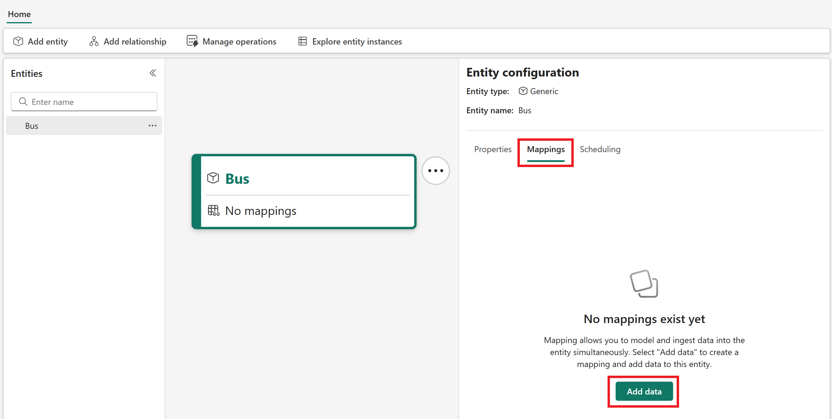
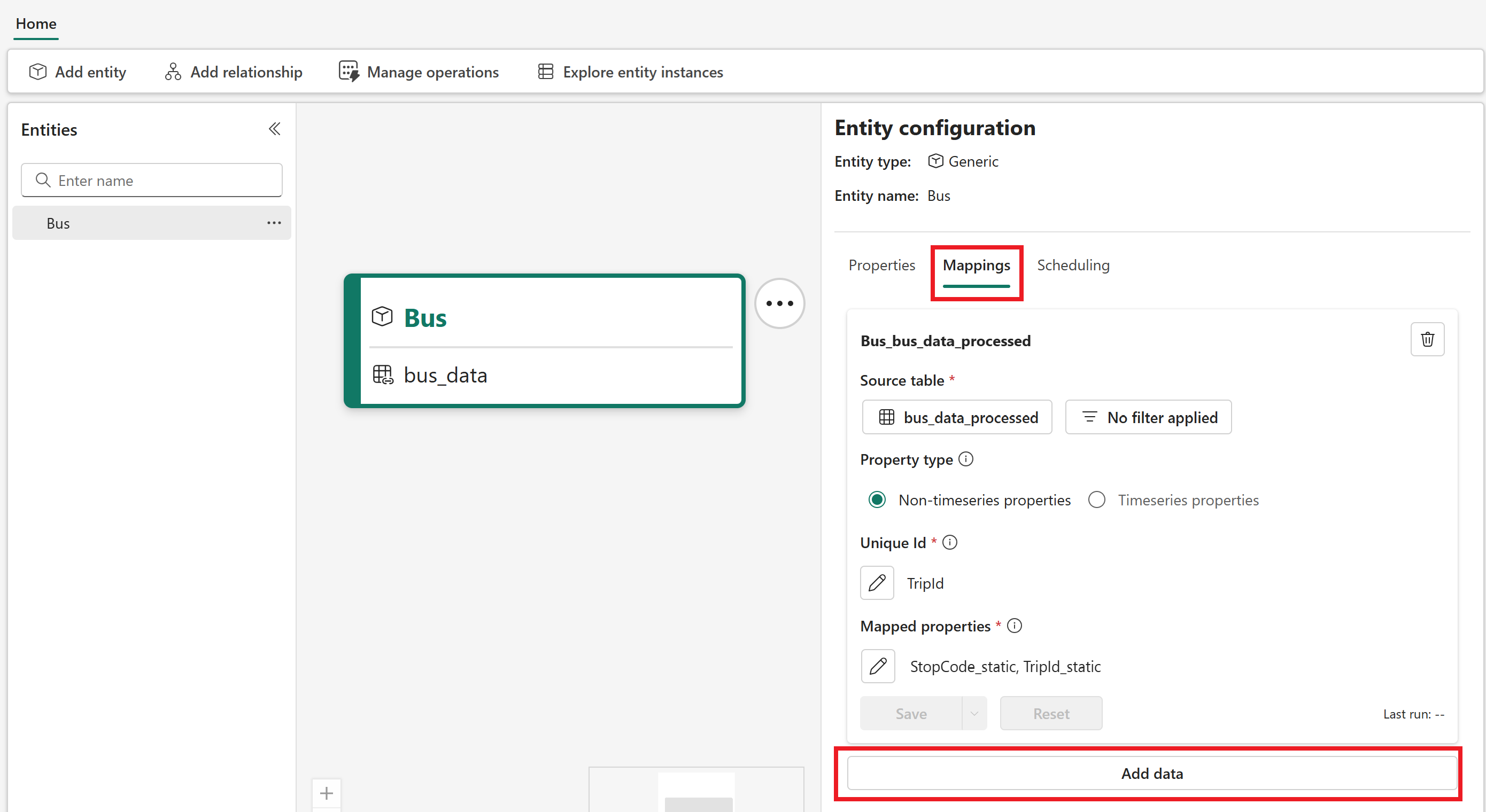
Map non-timeseries bus data
Next, map some non-timeseries data to the Bus entity type. These fields are static properties that identify a bus and its visit to a certain stop.
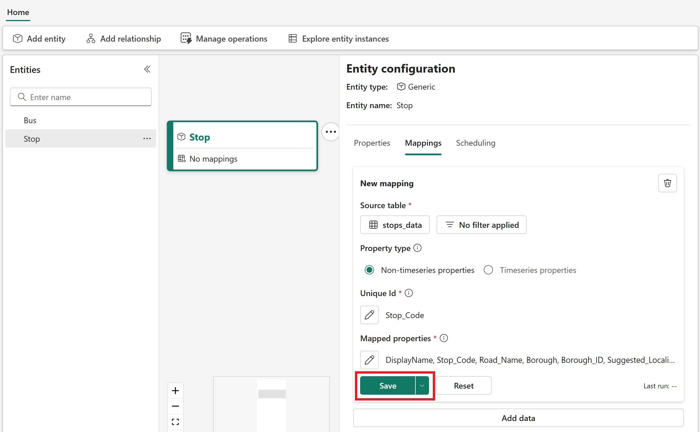
In the Entity configuration pane, switch to the Mappings tab and select Add data.
Open Select lakehouse table to select a data source for your mapping. Select your tutorial workspace, the TutorialLH lakehouse, and the bus_data_processed table.
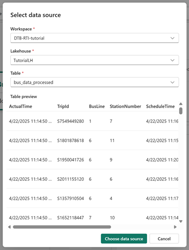
Optionally, wait for the data preview to load. Select Choose data source to confirm.
For the Property type, leave the default selection of Non-timeseries properties.
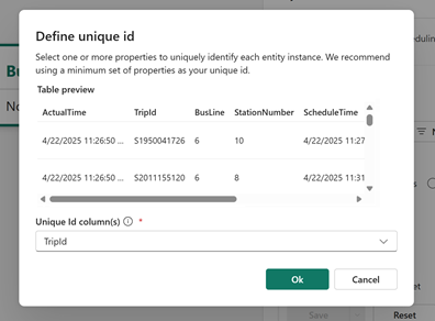
Under Unique Id, select the edit icon (shaped like a pencil) to choose a unique ID out of one or more columns from your source data. Digital twin builder uses this field to uniquely identify each row of ingested data.
Select TripId as the unique ID column.
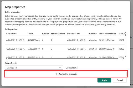
Under Mapped properties, select the edit icon to choose which properties from your source data to map to the bus entity type.
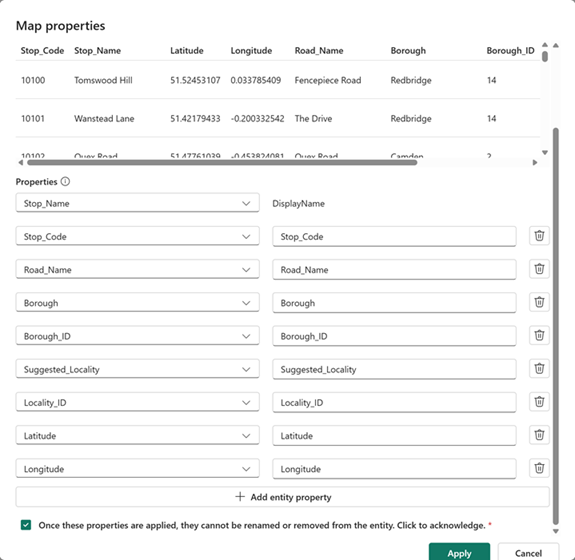
The Map properties page lets you select a column from your source data on the left side, and map it to a new property on your entity type on the right side. By default, selecting a column name from the source data on the left side fills in the right side automatically with a matching name for the entity type property, but you can enter a new name for the property on the right side if you want the entity type property to be named something different than what it's called in the source data.
The page loads with a DisplayName property for the entity type, which is unmapped to any column in the source data. Leave the DisplayName property unmapped as it is, and select Add entity property to add new properties to the mapping.
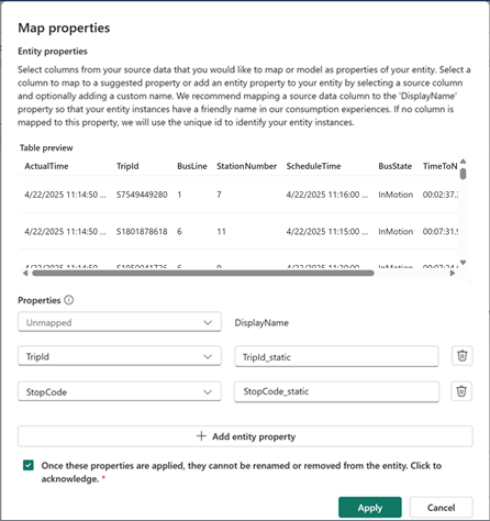
Map the following entity type properties:
- Select TripId from the dropdown menu in the left column, and edit the box across from it in the right column to read TripId_static. This action creates a property on the bus entity type named TripId_static, which gets its value from the TripId property in the source data.
- Select StopCode from the dropdown menu in the left column, and edit the box across from it in the right column to read StopCode_static. This action creates a property on the bus entity type named StopCode_static, which gets its value from the StopCode property in the source data.
Check the box to acknowledge that properties can't be renamed or removed, and select Apply.
Save the mapping.
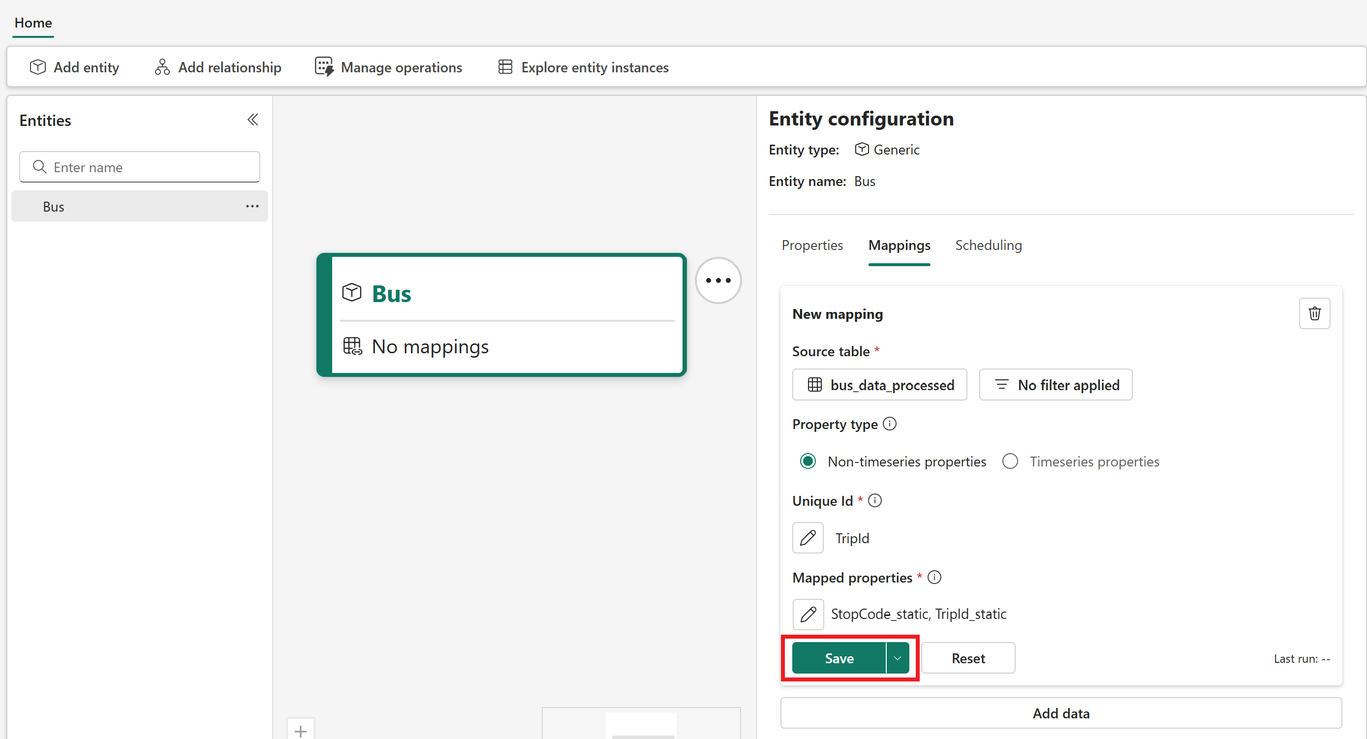
Switch to the Scheduling tab and select Run to apply the mapping.
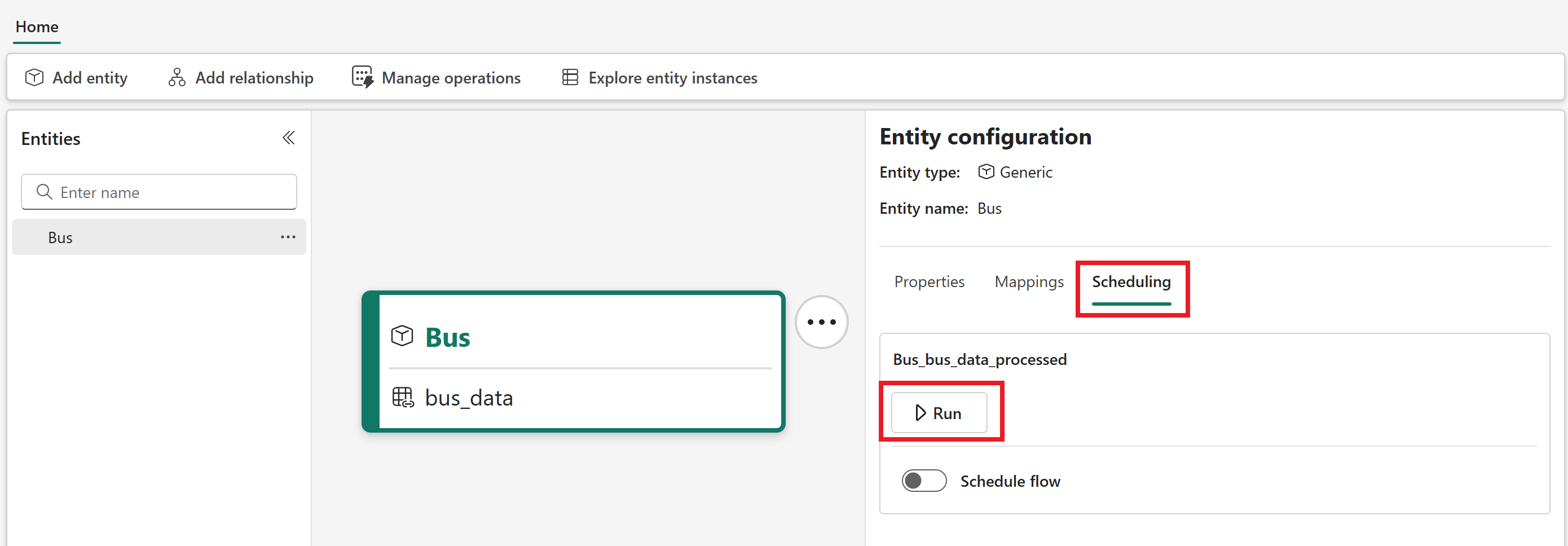
The page confirms that the flow is queued.
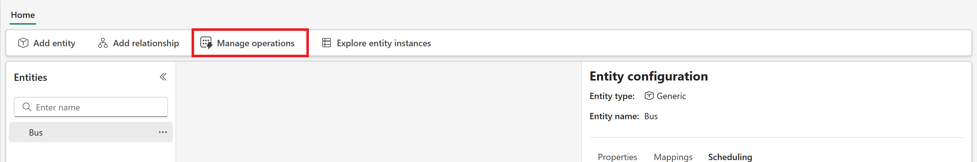
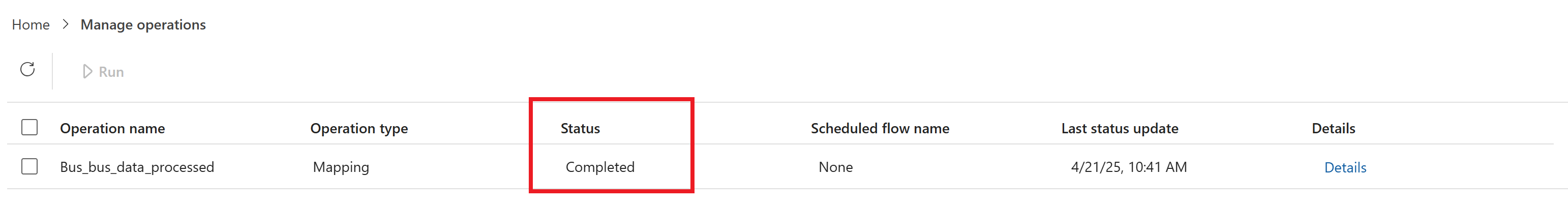
Check the status of your mapping job in the Manage operations tab. Wait for the status to say Completed before proceeding to the next section (the operation might take several minutes to begin running from the queue, and several more minutes to complete once it starts, so you might need to refresh the content a few times).
Map time series bus data
Next, map some time series data to the Bus entity type. These properties are streamed into the data source from the Eventstream sample data, and they contain information about the bus's location and movements.
Select Home to return to the semantic canvas, and reselect the Bus entity type. In the Entity configuration pane, reopen the Mappings tab. Select Add data to add a new mapping.
Open Select lakehouse table to select a data source for your mapping. Again, select your tutorial workspace, the TutorialLH lakehouse, and the bus_data_processed table. Select Choose data source.
This time, switch the Property type to Timeseries properties.
Under Mapped Properties, select the edit icon.
The page loads with a Timestamp property for the entity type, which is unmapped to any column in the source data. Timestamp requires a mapping, so select ActualTime from the corresponding dropdown menu on the left side. Then, select Add entity property to add new properties to the mapping.
Map the following properties. When you select these property names from the source columns on the left side, leave the default matching names that populate on the right side.
- ScheduleTime
- BusLine
- StationNumber
- StopCode
- BusState
- TimeToNextStation
- TripId
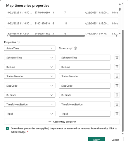
Check the box to acknowledge that properties can't be renamed or removed, and select Apply.
Next, link your time series data to this entity type. This process requires you to select an entity type property and a matching column from your time series data table. The column selected from the time series data must exactly match data that is mapped to the selected property on your entity type. This process ensures correct contextualization of your entity instance and time series data.
Under Link with entity property, select the edit icon.
For Choose entity property, select TripId_Static from the dropdown menu. For Select column from timeseries data..., select TripId. Select Apply.
Make sure Incremental mapping is enabled and Save the mapping. Confirm when prompted.
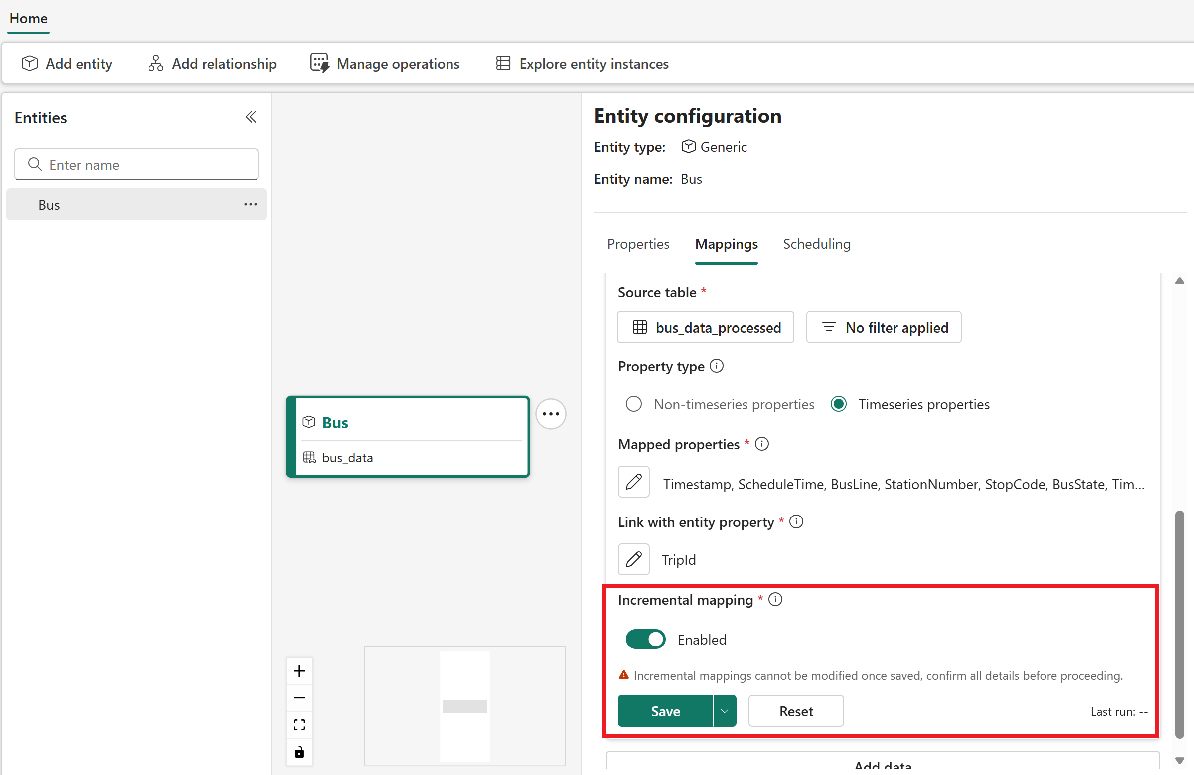
Switch to the Scheduling tab and select Run under the new time series mapping to apply it.
Add Stop entity type
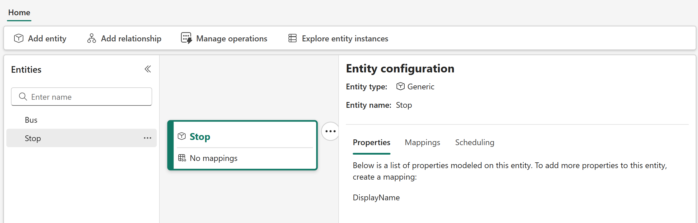
Next, create a second entity type to represent a bus stop.
In the semantic canvas, select Add entity.
Leave the Generic system type selected, and enter Stop for the entity type name. Select Add entity.
After a few minutes, the Stop entity type is now visible on the canvas.
Map non-timeseries stop data
Next, map some non-timeseries data to the Stop entity type. The stop data doesn't contain any time series data, only static data about the bus stops and their locations. Later, when you link the Stop and Bus entity types together, this data is used to enrich the bus fact data with dimensional data.
In the Entity configuration pane, open the Mappings tab and select Add data.
Open Select lakehouse table to select a data source for your mapping. Select your tutorial workspace, the TutorialLH lakehouse, and the stops_data table.
Select Choose data source.
For the Property type, leave the default selection of Non-timeseries properties.
For the Unique Id, select Stop_Code.
For Mapped properties, map Stop_Name from the source data to the DisplayName property on the right side.
Then, add the following new properties to the mapping. When you select these property names from the source columns on the left side, leave the default matching names that populate on the right side.
- Stop_Code
- Road_Name
- Borough
- Borough_ID
- Suggested_Locality
- Locality_ID
- Latitude
- Longitude
Check the box to acknowledge that properties can't be renamed or removed, and select Apply.
Save the mapping.
Switch to the Scheduling tab and select Run to apply the mapping.
Define relationship type
Next, create a relationship type to represent that a Bus goesTo a Stop.
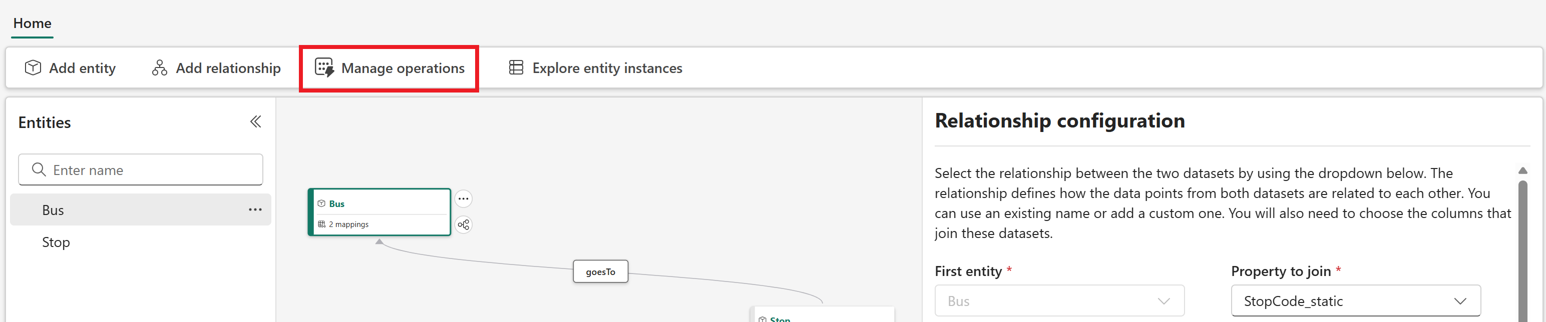
In the semantic canvas, highlight the Bus entity type and select Add relationship.
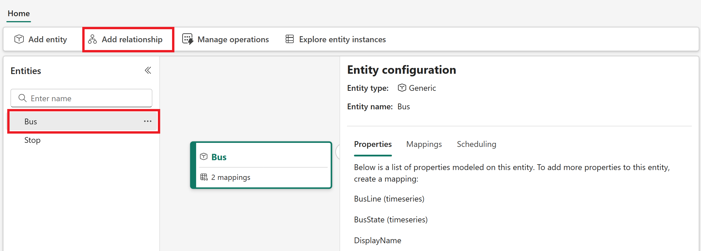
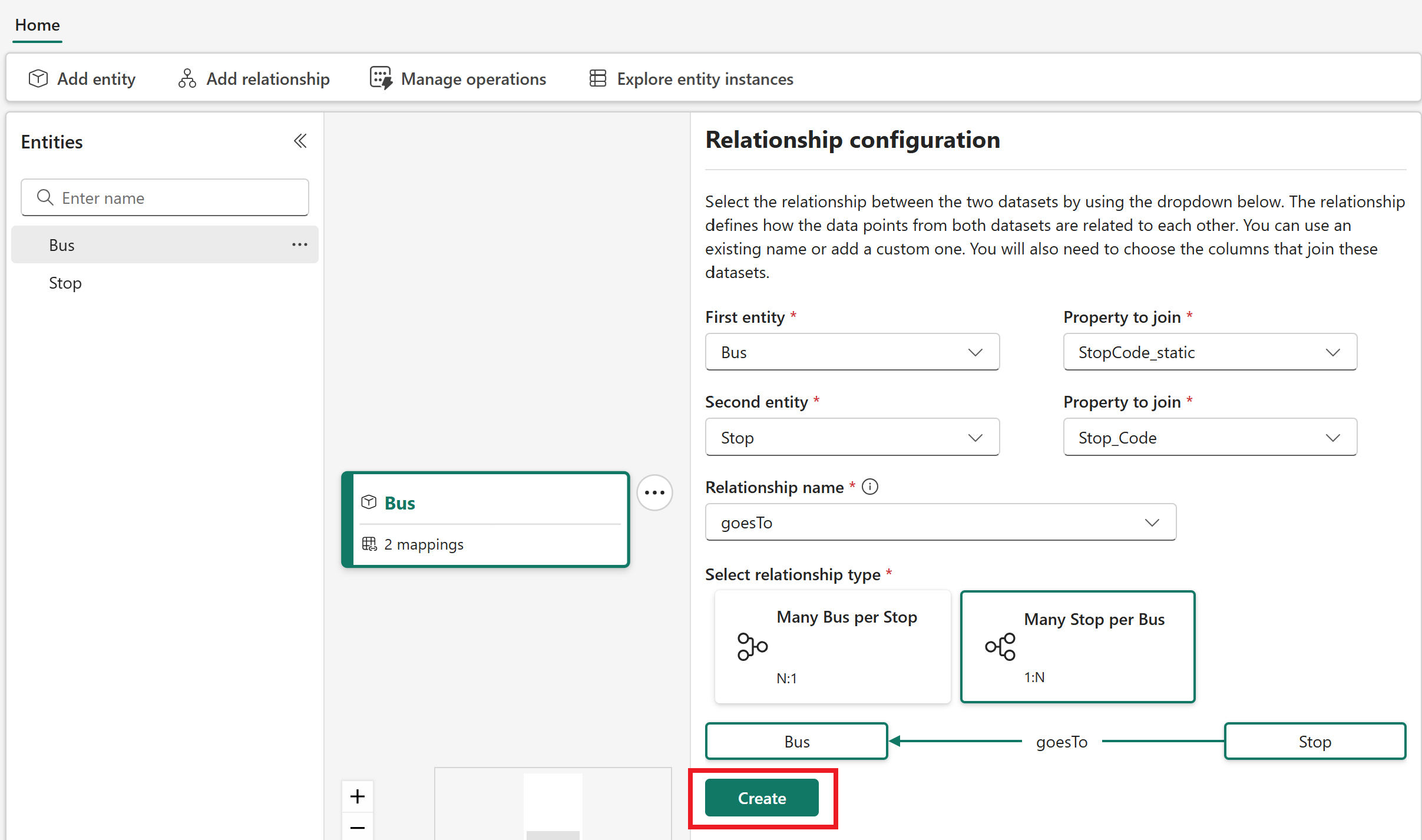
In the Relationship configuration pane, enter the following information:
- First entity: Bus
- Property to join: StopCode_static
- Second entity: Stop
- Property to join: Stop_Code
- Relationship name: Enter goesTo
- Select relationship type: Many Stop per Bus (1:N)
Select Create.
- First entity: Bus
In the Scheduling section that appears, select Run to apply the relationship type.

Now your Bus and Stop entity types are visible in the canvas with a relationship type between them. Together, these elements form the ontology for the tutorial scenario.

Verify mapping completion
As a final step, confirm that all your data mappings ran successfully. Each mapping might take several minutes to run.
From the menu ribbon, select Manage operations.
View the details of the mapping operations, and confirm that they all completed successfully.
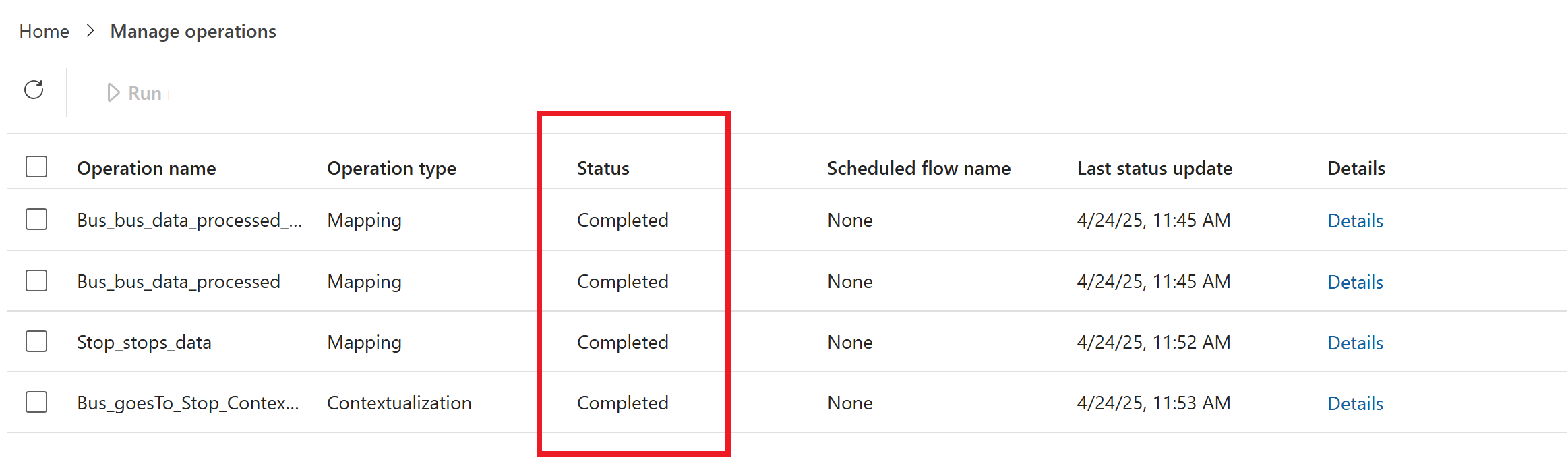
If any of the operations failed, check the box next to its name and select Run to rerun it.
Wait for all mappings to complete before you move on to the next part of the tutorial. In the next part, you project the ontology that you mapped to an eventhouse, to support further data analysis and visualization.