Note
Access to this page requires authorization. You can try signing in or changing directories.
Access to this page requires authorization. You can try changing directories.
This article helps you to work with a simple experiment of connecting LED lights with Raspberry Pi device (device only with Windows 10 IoT Core OS)
Requirements:
- Raspberry Pi 2/3 with Windows 10 IoT Core OS connected to internet
- Laptop or PC with Windows 10 OS connected to internet
- Visual Studio 2015 installed on your laptop or PC
- Bread Board
- LED Light
- Resistor
Follow the below steps:
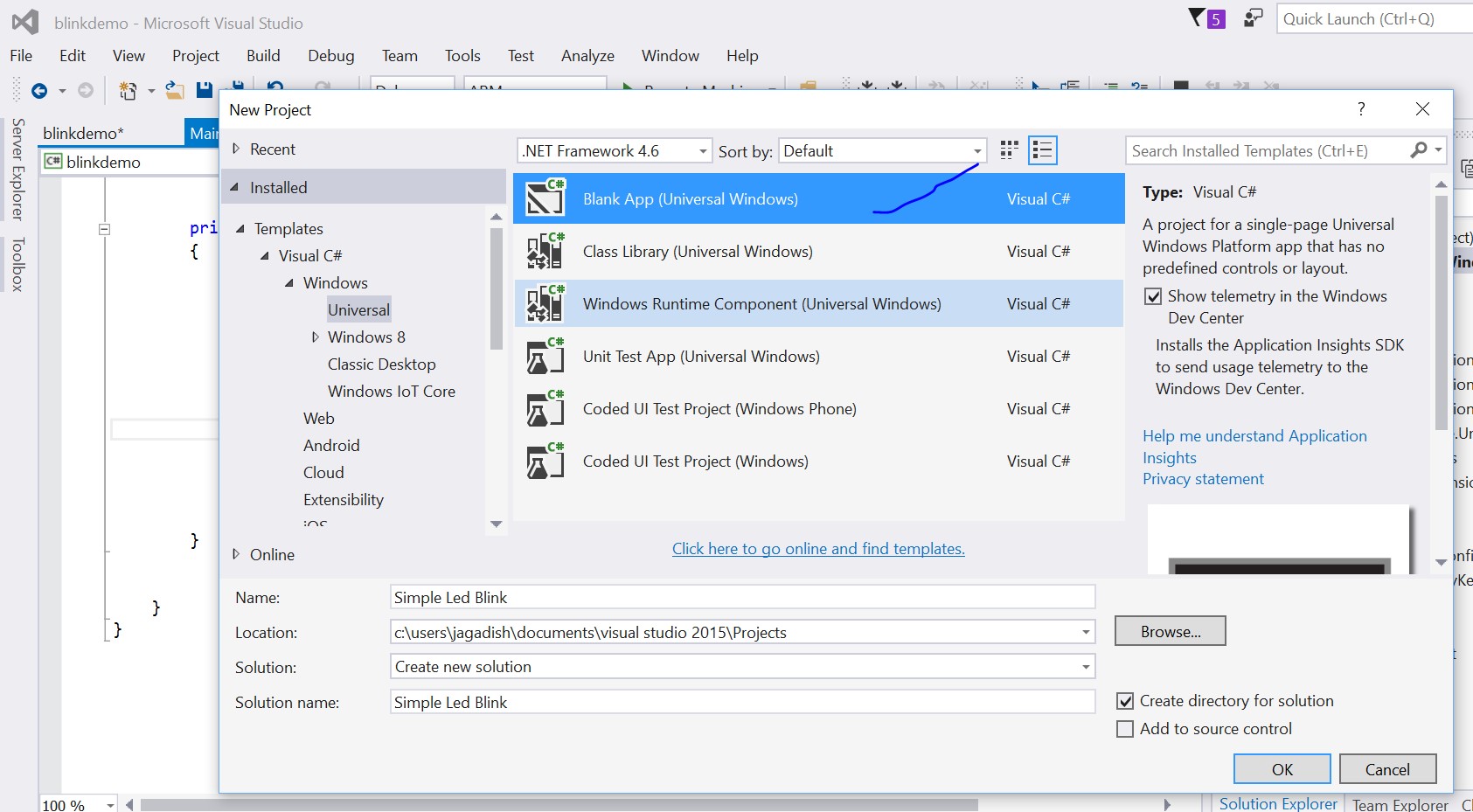
**Step – 01: **Select File -> Create new project -> Name it "Simple Led Blink"
** **
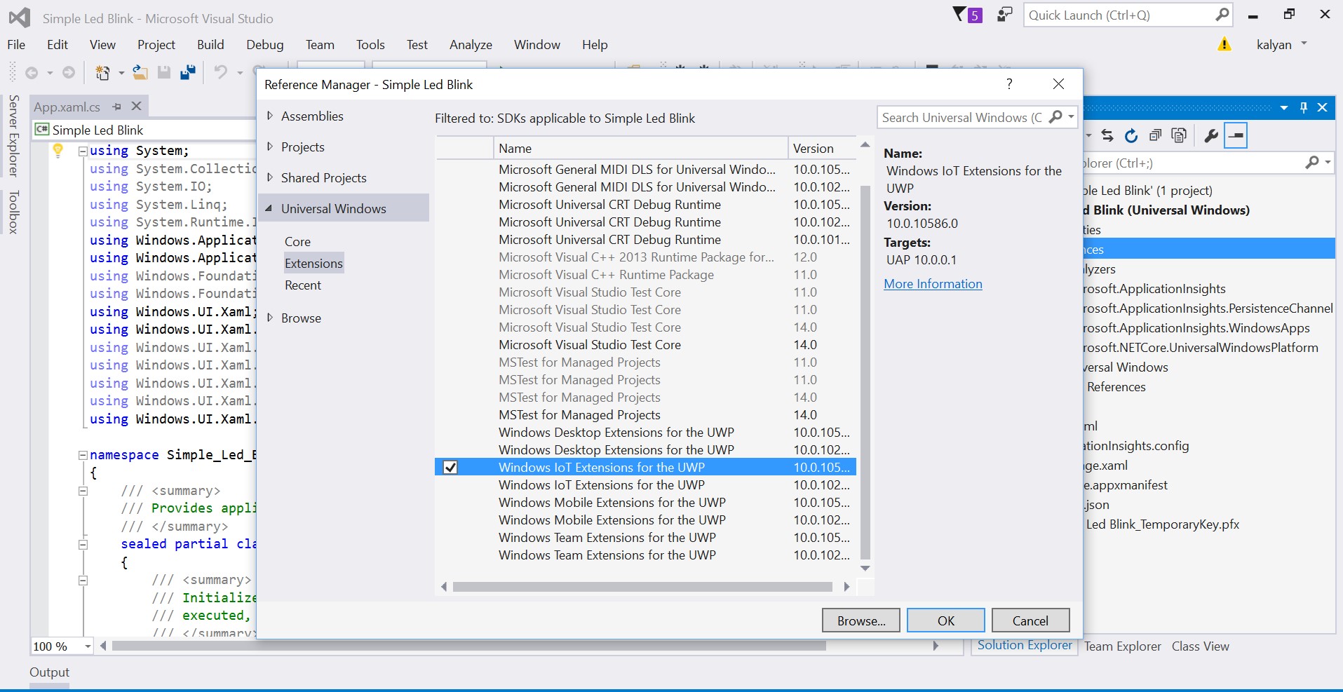
**Step – 02: **Right click on the selection and add reference. Select Windows IoT Extention for the UWP and click ok.
**Step – 03: **Open MainPage.xaml and add the following for UI
<Grid Background="Wheat">
        <StackPanel HorizontalAlignment="Center" VerticalAlignment="Center">
            <Ellipse x:Name="LED" Fill="LightGray" Stroke="White" Width="100" Height="100" Margin="10"/>
            <TextBlock x:Name="DelayText" Text="500ms" Margin="10" TextAlignment="Center" FontSize="26.667" />
            <TextBlock x:Name="GpioStatus" Text="Waiting to initialize GPIO..." Margin="10,50,10,10" TextAlignment="Center" FontSize="26.667" />
        </StackPanel>
    </Grid>
**Step – 04: **Open the MainPage.xaml.cs add the following in the cs file.
    private const  int LED_PIN =5;
    private GpioPin pin;
    private GpioPinValue pinValue;
    private DispatcherTimer timer;
    private SolidColorBrush redBrush = new SolidColorBrush(Windows.UI.Colors.Red);
    private SolidColorBrush grayBrush = new SolidColorBrush(Windows.UI.Colors.LightGray);

    public MainPage()
    {
        InitializeComponent();

        timer = new  DispatcherTimer();
        timer.Interval = TimeSpan.FromMilliseconds(500);
        timer.Tick += Timer_Tick;
        InitGPIO();
        if (pin != null)
        {
            timer.Start();
        }
    }

    private void  InitGPIO()
    {
        var gpio = GpioController.GetDefault();

        // Show an error if there is no GPIO controller
        if (gpio == null)
        {
            pin = null;
            GpioStatus.Text = "There is no GPIO controller on this device.";
            return;
        }

        pin = gpio.OpenPin(LED_PIN);
        pinValue = GpioPinValue.High;
        pin.Write(pinValue);
        pin.SetDriveMode(GpioPinDriveMode.Output);

        GpioStatus.Text = "GPIO pin initialized correctly.";

    }

    private void  Timer_Tick(object  sender, object  e)
    {
        if (pinValue == GpioPinValue.High)
        {
            pinValue = GpioPinValue.Low;
            pin.Write(pinValue);
            LED.Fill = redBrush;
        }
        else
        {
            pinValue = GpioPinValue.High;
            pin.Write(pinValue);
            LED.Fill = grayBrush;
        }
    }

}
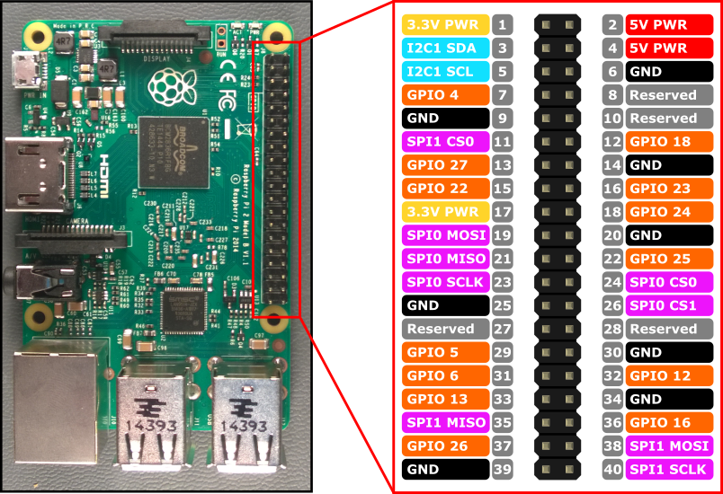
In the above code we are using the GPIO(General purpose input output ports) for the interaction of the electronic circuit. We are using GPIO 5 over here
Connect the following circuit
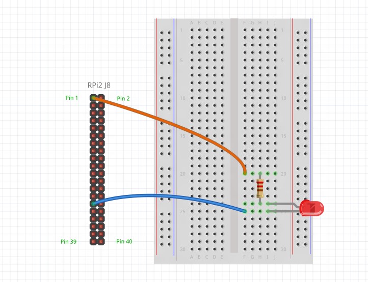
Once the circuit is connected, build the solution.
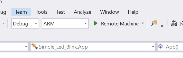
**Step – 05: **Now build the solution and select ARM and select Remote Machine
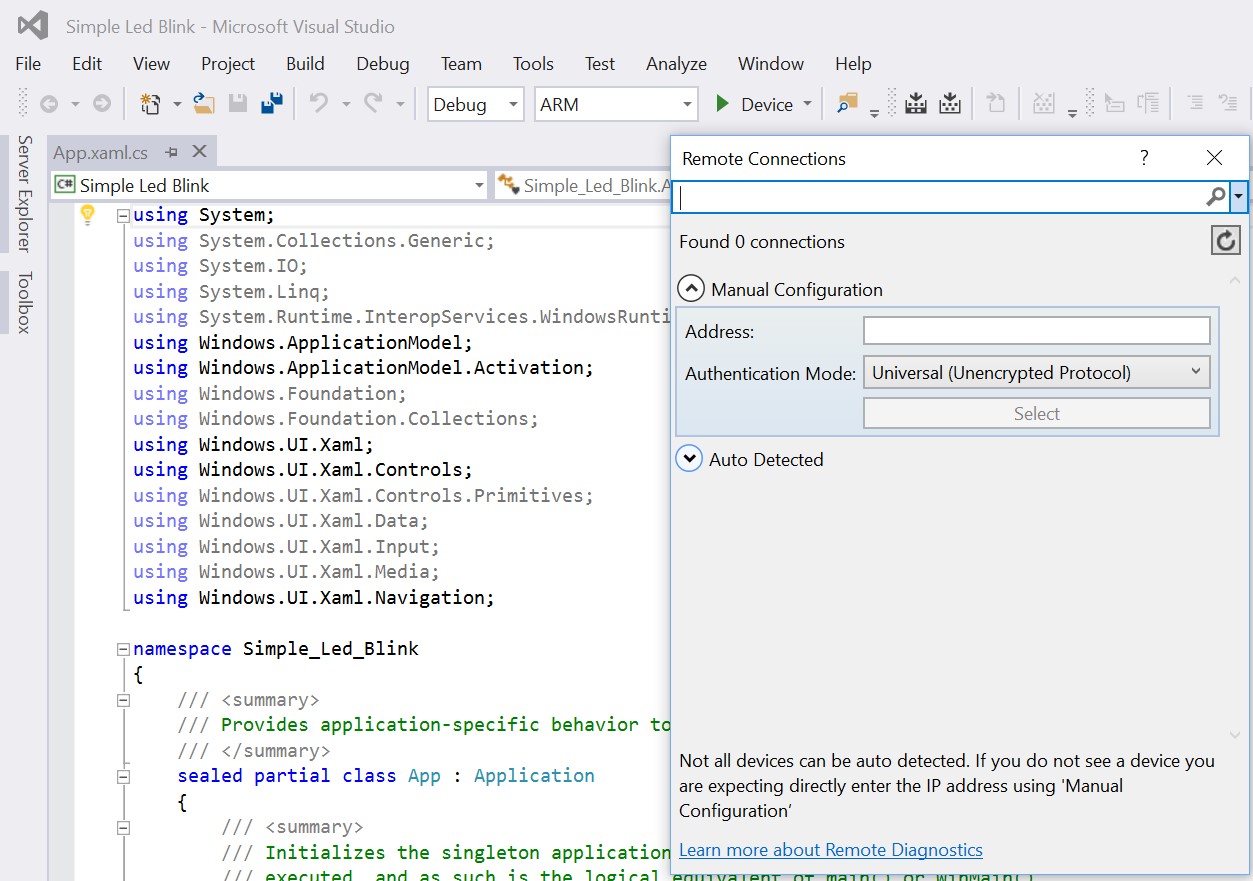
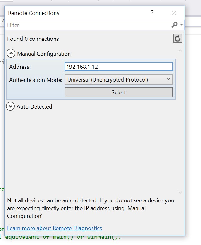
In the address column enter the ip address of the network connected with Raspberry Pi device and click ok.
**Step – 06: **Now once Remote Machine is selected build and run the application. Once the application is build & run operation is completed successfully in the sense you will find the LED blinking according to the timer set.